Structural analysis of sewers and drains – what will change?
Worksheet A 127 is currently under revision, analogously to the already completed DWA-A 161. The aim of this paper is to discuss briefly the most significant changes in DWA-A 127-1, which correspond to the editing status of December 2017. Publication of the preliminary yellow copy is planned for 2018.
A number of minor changes
The material properties for all related DWA regulations are transferred to DWA-A 127-10. The semi-probabilistic safety concept with partial safety factors will be introduced analogously to the European standards and DWA-A 161. General notes are given for application of numerical analyses (finite element method). The new designations A0 instead of A4, and B0 instead of B4, are purely formal to achieve a logical sequence (decreasing compaction) of the installation conditions. Sub-groups analogous to DWA-A 161 are introduced for designating in-situ soils. Classification of backfill remains as it is. The internal friction angle for G4 (cohesive soil) is reduced from 20° to 15°.
Intermittently flowable, self-compacting backfilling materials (ZfsV)
Utilization of self-compacting backfilling materials (ZfsV) can be calculated only with A 127, if behavior similar to soil exists even after complete hardening. This condition must be verified based on a data sheet (for example, deformation module EB as a function of time). Additional as-built checks for buoyancy and safety against buckling must be performed. The design supporting angle is 2α = 120° or 90° when using sheet piling. As a benefit, αB = f1 = f2 = 1 may be applied. A calculated minimum limit applies to a trench width of bg = da + 2 x 0.15.
Consideration of underramming in sheet piling
Until now, attention was called to worksheet ATV-AG 1.5.5 for taking this effect into account. Now the increase projection is limited to as ≤ 2 and as ≤ ar + bg/da. The latter limits the maximum influence of underramming to the center of the trench. Factor as increases the load concentration on the pipe. In addition, factor ks is limited: it takes into account the reduction of the support angle and the load concentration in the center of the top of the pipe. Factor ks = 1.3 is replaced by ks = 1 for ≤ DN 800 and ks = 1.2 for ≥ DN 1200. Interim values may be interpolated. This measure favors all pipe dimensions by at least 8%, and smaller pipes by significantly more.
New live loads
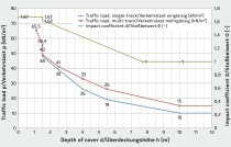
For live loading, the horizontal supporting effect due to live loading may now also be applied in reduced form, since the impact (oscillation) coefficients included may be eliminated in calculation – i.e., 1.2 for street traffic and 1.5 for air traffic – and/or reduced to redΦ2.H,dyn = 0.5 (redΦ2 + 1) for railway traffic. The lateral pressure coefficient will assumably be accounted for with k2 = 0.4. For the permissible steel stress for welded reinforcement, the new and much more stringent values of DIN EN 1992-1-1/NA will now apply for the fatigue check (e.g., for 2 x 10⁶ load cycles the applicable value of 64.3 N/mm² instead of the previous 80 N/mm²). The road traffic loads according to DIN 1072 will be replaced by load model LM1 and fatigue load model 3 (approx. 40 % of LM 1) from DIN EN 1991-2. LM 1 is a tandem axis with wheel loads of 150 kN on 0.4 x 0.4m with a center-to-center distance of 1.2m. These new stipulations take into account several traffic lanes and narrow roadways. The load height can be further varied by the adjustment coefficient αQ. With αQ = 0.8, the same wheel loads can be achieved as with SLW 60; however, with reduced center-to-center distance. Since LM 1 is considered as substitute load for bridges, which cannot be directly compared with loads through pipes, αQ = 0.8 may be quite sufficient. On a critical note it may be stated that road traffic loads depend on the effective pipe length and that there is a jump in the backfill height of 1m in the load curve. In addition, the positive support effect is determined on the basis of only one wheel load, whereas the load is determined on the basis of two traffic lanes (8 wheel loads). The railroad live loads are slightly changed from the old version, analogous to RIL 836; significantly increased oscillation coefficients are given, as well as a backfill cover of between 1.1m and 1.5m. The fatigue check must in general be performed for 108 load cycles (see ELTB). The loading on pipes laid parallel to the tracks depends on the position in the internal and external compressive areas. The fatigue check can be performed here, if necessary, based on a lower number of load cycles, or can be altogether eliminated.
Summary
A revision of DWA-A 127 became necessary to establish conformity with the current European body of regulations (e.g., partial safety coefficients and live loading), to take account of changes in railroad regulations, to make improvements (for example for underramming), and to include supplements (e.g., Zfs backfill materials and pipelines laid parallel to railroad tracks).


