Reinforcement planning with high adjustment convenience
Ongoing planning during construction is increasingly becoming standard procedure. CAD solutions for structural design, reinforcement and precast production and erection planning make it possible to react flexibly to short-term changes and to avoid errors.
Requests for significant changes to the structural design by clients, architects and planners of technical building services generate high costs. Even relatively minor changes to a construction element can trigger a whole chain of additional changes. Errors discovered shortly before commencement of construction, production or erection not only can cost a great deal of money, but damage the reputation of the planner as well. State-of-the-art CAD software, such as Strakon 2014 from Dicad, simplify the follow-up work necessitated by changes so that the user, thanks to the high adjustment convenience, can exclusively concentrate on planning control.
Planning security for change requests
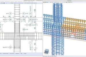
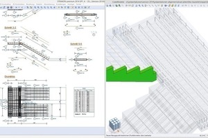
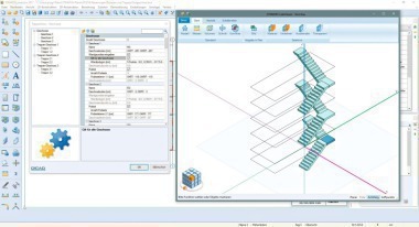
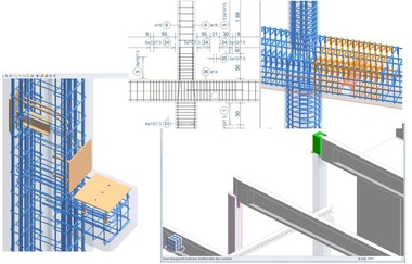
Intelligent construction products, editing functions and automatisms implement modifications and follow-up changes in a plan largely automatically. Because the reinforcement is associatively linked to the geometry of a construction element, all reinforcement drawings, summaries and cutting lists are automatically adapted to the changed geometries of the construction elements. This applies equally to 2D or 3D planning and to ordinary or complex standard construction elements. If, for example, the stair flights become wider, the 3D reinforcement, all edge formwork, reinforcement drawings, steel and bending lists are automatically adjusted – including dimensioning, labelling and hatchings. When an opening in a construction element in the 3D model is changed, the change is automatically implemented, or reversed, in the construction plan, detail drawing, production and erection plan.
By means of the reinforcement check, all additionally changed bar positions or placements can be controlled. In this manner, for example, nodal points can be checked to confirm that all of the steel bars and mesh reinforcement were correctly changed. Reinforcement drawings such as, for example, sections, elevations, plans or bottom views are automatically derived from the 3D model as “3D views”. The drawings and plans generated in that manner remain linked to the model so that any subsequent modifications are automatically considered.

