Tensile behavior of concrete components reinforced with natural-fiber textiles
In a research project funded by the Deutsche Bundesstiftung Umwelt (DBU; German Federal Environmental Foundation), the structural behavior of concrete components reinforced with textiles made of flax fibers under uniaxial tensile and flexural loading is being investigated. This article presents the preliminary results of tensile tests involving specimens with two and three layers of reinforcement and varied degrees of weft fineness.
In a research project funded by the Deutsche Bundes-stiftung Umwelt (DBU; German Federal Environmental Foundation), the structural behavior of concrete components reinforced with textiles made of flax fibers under uniaxial tensile and flexural loading is being investigated. This article presents the results of tensile tests involving specimens with two and three layers of reinforcement (non-impregnated leno weaves) and varied degrees of weft fineness. The load-displacement diagrams show that the curves can be divided into three main areas: State I (uncracked condition), State IIa (progression of cracking), and State IIb (final cracking pattern). This subdivision becomes more evident as the reinforcement ratio increases. In addition, a significant increase in bearing capacity was achieved for the more strongly reinforced specimens compared to tensile tests performed on unreinforced specimens or specimens with a low reinforcement ratio, and a uniformly distributed cracking pattern was documented.
1 State of the Art
More sustainable construction methods and the use of renewable raw materials play an ever-greater role in the construction industry. Among other options, non-metallic types of reinforcement have become increasingly relevant since they allow for designing slender, lightweight structures. The structural behavior of such concrete components reinforced with AR-glass or carbon fibers, for example, was studied fundamentally on a national scale in two collaborative research centers (SFB 528 and SFB 532) [1]-[6]. In subsequent transfer projects, increasingly complex applications were implemented [7]-[12]. The C3 (Carbon Concrete Composite) project, which started in 2014 and is currently nearing completion, aims to establish the more widespread use of carbon-reinforced concrete in the construction industry [13] and to draft a guideline for designing textile-reinforced components in order to replace the complex experimental tests necessary for determining the load-bearing capacity by a computational verification method similar to the approach applied to steel-reinforced structures [14]-[19].
At the current stage, however, the draft guideline referred to above does not include textiles made of natural fibers. Notwithstanding, international research activities increasingly focus on concrete components reinforced with natural fibers [20]-[23]. Besides studies on mostly planar 2D structures composed of renewable fibers from plants that can be grown in (sub)tropical regions (such as sisal, jute, or coconut) [24]-[27], some initial research projects are currently investigating the mechanical characteristics of flax fiber textiles in cement-based composites [28]. Yet the authors are not aware of any structural models or design rules for concrete reinforced with natural fiber textiles described in the literature they could access, such as those to be developed in the current DBU-funded project.
Generally, textile reinforcements provide the advantage of their non-existent or significantly reduced susceptibility to corrosion while reaching the same or even higher tensile strength levels compared to reinforcing steel. Accordingly, the required nominal concrete cover can be minimized and cement can be saved, which makes a major contribution to mitigate the associated environmental impact. Furthermore, compared to synthetic fibers, the use of renewable fibers brings a number of additional benefits, such as reduced carbon emissions in the production process, a more sustainable material cycle [29] or less sophisticated occupational health and safety requirements [30].
The tests described in the following sections form part of the “Investigation of sustainable reinforcements made of natural fibers for textile concrete components (laboratory phase)” research project, which is funded by the Deutsche Bundesstiftung Umwelt (DBU; German Federal Environmental Foundation). In addition to investigations into the recyclability of the novel composite material, the project aims to derive conclusions regarding the bond and tensile behavior as well as the uniaxial flexural behavior of concrete components with a textile reinforcement made of flax fibers. This article presents the results of the experimental tests carried out to date on the bond and tensile behavior of test specimens with multiple layers of reinforcement and varying yarn structures.
2 Experimental tests
2.1 Materials used
An optimized concrete/mortar was developed [32] since standard concrete mixes conforming to DIN EN 206 [31] were unsuitable for this project due to the limited opening width of the embedded textiles. The developed C5 mortar concrete meets both the requirements of being sufficiently workable (in terms of flowability and fabric penetration, for example) and providing the necessary mechanical properties (such as a sufficiently high tensile and compressive strength). Table 1 summarizes the constituents as well as the key strength values of the mix. The uniaxial tensile strength was calculated according to the fib Model Code for Concrete Structures 2010 [33] from the flexural tensile strength values determined in the experimental phase.
Together with the test specimens, six prisms measuring 160 × 40 × 40 mm were made from the same batch of concrete in accordance with DIN EN 196-1 [34] to determine the flexural tensile and compressive strength of the concrete on the day of the tensile tests. The specimens were stripped on the day after concrete pouring and stored in a water bath until day 14. They were then stored under constant conditions (20 °C, 60% relative humidity) and tested on day 28.
In textile-reinforced concrete components, the textile reinforcement is primarily subjected to tensile loads, which makes the analysis of its tensile behavior is crucial for characterizing the composite and for using it in the most appropriate manner. The flax fiber weft threads used in the specimens are characterized by yarn tensile tests according to ASTM D 2256 [35] /DIN EN ISO 2062 [36].
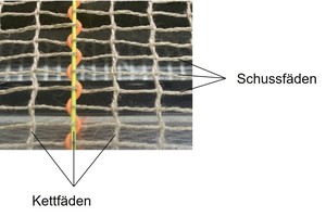
The textiles produced as leno weaves on a double-rapier weaving machine with Jacquard attachment at the Fraunhofer WKI consisted of flax fiber yarns. In a leno weave, two threads are combined in the warp direction (machine direction), namely the ground thread, which runs perpendicular to the weft thread, and the leno thread, which takes a 180 degree turn around the ground thread after each weft thread and enclosing it (see Fig. 1 (a)).
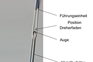
This twist is created by special healds referred to as leno healds through which the warp material is passed. The ground thread is located in the eye of the metal half-heald and the leno thread sits above it in the guide unit of the entire leno heald, which is made of plastic (Fig. 1 (b)). The up-and-down movement of the heald creates a stroke that moves the leno thread to the right and left, thus, creating the twist that makes leno weaves much more resistant to displacement than other conventional 2D fabrics as those with a plain weave, provided wide yarn spacings, such as in this project, are specified. In addition, this type of fabric minimizes the waviness of the weft threads, which causes less damage to the yarns during the waving process [37].
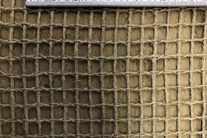
The tested weaves consisted of weft threads with a fineness of 1000, 1200, and 1500 tex, respectively, while the ground and leno threads running in the warp direction each had a fineness of 500 tex. In addition, the textiles had an opening width of 8 mm in the weft direction and of 10 mm in the warp direction, resulting in reinforcement cross-sectional areas of 89.3 mm²/m, 107.1 mm²/m, and 133.9 mm²/m, respectively. In the tests described in this article, non-impregnated textiles (Fig. 2) were used whose tensile strength amounted to approximately 300 MPa (see Table 2).
2.2 Test setup
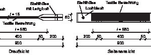
The tensile tests were carried out on bone-shaped specimens that had already been used in similar tests of synthetic fibers [2], [6], [38]-[40]. Since the non-impregnated textile reinforcement made of natural fibers has a larger cross-sectional area than comparable textiles made of synthetic fibers, a web width of 15 mm in the free strain length was chosen. Fig. 3 shows the geometry of the test specimens. The gauge length for measuring the specimen’s strain was set to 580 mm.
Two or three layers of textile reinforcement were incorporated in the specimens, depending on the fineness of the weft threads. Accordingly, six test series with four specimens each were carried out, as shown in Table 3.
Prior to concrete pouring, the end sections of the textiles were glued onto 2 mm thick perforated plates such that the reinforcement layers could be installed axially and orthogonally to the anticipated direction of cracking. Since the non-impregnated textiles used in the tests are much less dimensionally stable than their impregnated counterparts, the reinforcement was slightly tensed in the form prior to concreting, which prevented the individual threads from aligning and stretching in the tensile direction only during the test as such. This procedure activated the non-impregnated textiles more effectively, thus allowing for better absorption and transfer of tensile stresses.
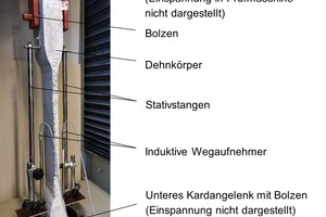
Fig. 4 shows a tensile test specimen installed in the electromechanical universal testing machine (ZwickRoell, type UPM, maximum tensile force 200 kN) before the test. Universal joints were used to ensure axial load application. During the tests, loads and displacements were measured continuously at 5 Hz using a load cell and two inductive displacement transducers (LVDT, see Fig. 4) attached to the sides of the specimens.
3 Test results
3.1 Load-displacement diagrams
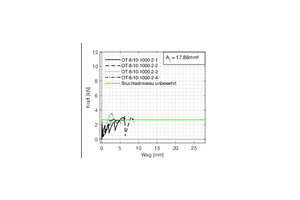
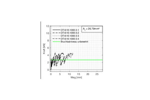
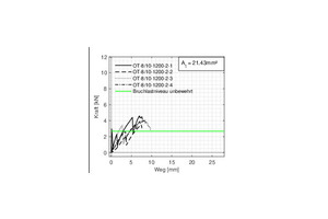
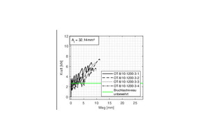
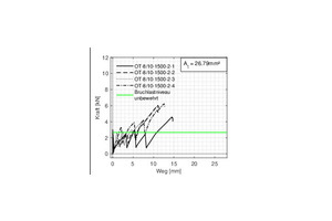
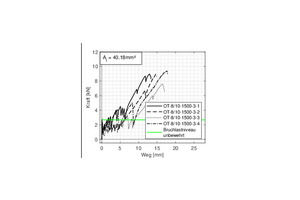
For the purpose of analyzing the tensile test results, measured loads were plotted against the mean values captured by the two displacement transducers. Figs. 5 (a), (c) and (e) show the load-displacement diagrams of the specimens with two layers of reinforcement, whereas Figs. 5 (b), (d) and (f) include the corresponding diagrams of the specimens with three layers of reinforcement (in each case, subdivided according to the different weft finenesses). In addition, the diagrams include the mean ultimate load of an unreinforced specimen of approximately 2.67 kN that was determined in a series of tests on 12 unreinforced reference specimens (light green line).
3.2 Discussion
Three main conclusions can be drawn from the diagrams:
Firstly, the individual tests within a series each showed a similar course of the load-displacement curve, with similar failure loads and maximum displacements reached.
Secondly, the failure load of the more strongly reinforced tensile test specimens (starting from approx. At = 26.8 mm²) could be increased by a factor of up to 3 (cf. Fig. 5 (f)) compared to the mean of the unreinforced reference specimens. Likewise, the failure load level of the more strongly reinforced specimens could be increased significantly (by a factor varying between 1.8 and 3.0) compared to the reference specimens with a low reinforcement ratio (cf. Fig. 5 (c), (f)). The influence of the weft fineness was found to be greater than the influence of the number of reinforcement layers. Specimens OT-8/10-1000-3-x and OT-8/10-1500-2-x have the same reinforcement cross-sectional area of 26.79 mm², however, the load increase is more pronounced with two layers and a greater weft fineness (Fig. 5 (e)) than with three layers and a smaller fineness (Fig. 5 (b)). In addition, the failure load of the specimens with three reinforcement layers can be increased by about 50% relative to the two-layer reinforcement, which corresponds approximately to a load increase proportional to the existing reinforcement cross-sectional area. Similar results can be obtained for the different finenesses: The load can be increased by 30-40% relative to the smaller yarn cross-section.
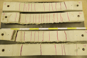
Thirdly, the test specimens show the typical behavior of a reinforced tensile specimen exhibiting different stages of crack formation. These stages can be clearly distinguished from each other, especially in the case of the more strongly reinforced specimens: In State I, the concrete cross-section is uncracked and the tensile load is almost exclusively transferred through the concrete. The strain in the concrete equals that in the textile reinforcement. The formation of the first crack triggers the phase of initial cracking (State IIa). The abrupt load drops in the load-displacement curves observed in State IIa indicate the formation of cracks. In the cracks, the load is absorbed and transferred by the textile. However, there are still areas in the component where the strains of the concrete and the textile reinforcement are equal, so that in these areas the tensile stresses in the concrete continue to increase with loading, and further cracks may develop in the concrete. Once the final cracking condition has been reached, a further increase in load to State IIb (final cracking pattern) can be observed, especially in the more strongly reinforced specimens. Yet, the loads introduced into the concrete via bond forces no longer exceed the tensile strength in any location, which explains the absence of further cracking. The continued increase in strain with loading leads to a significant crack width increase without further cracks forming. Finally, the sudden rupture of the textile causes the specimen to fail, which is preceded by a corresponding finely distributed cracking pattern (cf. Fig. 6) exhibiting considerable crack widths. In the diagrams, this can be derived from the load drop after the maximum load has been reached. The post-failure behavior results from the fact that the finitely long natural fibers of the textile’s yarns are pulled apart or torn off completely. This is caused by successive failure of the individual yarns, similar to the phenomenon documented in the test of the textile material [32].
4 Conclusion and outlook
The tests of the uniaxial tensile behavior of concrete components with a multi-layer textile reinforcement consisting of flax fibers presented in this article confirm that an effective bond behavior can already be achieved when using non-impregnated fabrics. With sufficiently large reinforcement cross-sections, a finely distributed cracking pattern with narrow crack spacing (approx. 3 to 8 cm) was obtained, and a significant load increase (up to a factor of 3) could be achieved compared to unreinforced specimens or specimens with a low reinforcement ratio. In addition, the progression of the load-displacement curves could be subdivided into three main States (I: uncracked; IIa: initial crack formation; IIb: final cracking pattern).
For subsequent tests on tensile specimens with reinforcements made of impregnated textiles, it is anticipated that the load can be increased even further due to the impregnation which causes, among other effects, an increase in the tensile strength of the textile. Since it can also be assumed that the bond behavior of the impregnated textiles in the concrete matrix is improved compared to that of the non-impregnated fabrics, an even more finely distributed cracking pattern is likely to occur.
5 Acknowledgements
The research presented in this article is funded by the Deutsche Bundesstiftung Umwelt (DBU, German Federal Environmental Foundation; 35830/01-25) – the authors would like to express their gratitude to the foundation. In addition, thanks are due to industry partners Sika Deutschland GmbH, sh minerals GmbH, a+b Asphalt- und Betonmischwerke GmbH & Co. KG and, in particular, Schwenk Zement GmbH & Co. KG for providing the materials and technical support. The authors also thank Felix Trah, M.Eng., who made a major contribution to the tests presented in this article as part of his Master thesis, and, last but not least, the project partner Fabrino Produktionsgesellschaft mbH & Co. KG, who manufactured the tensile test specimens.

