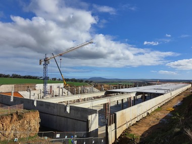
Massive Firewall built with Precast Concrete for Cape Fruit Distributor

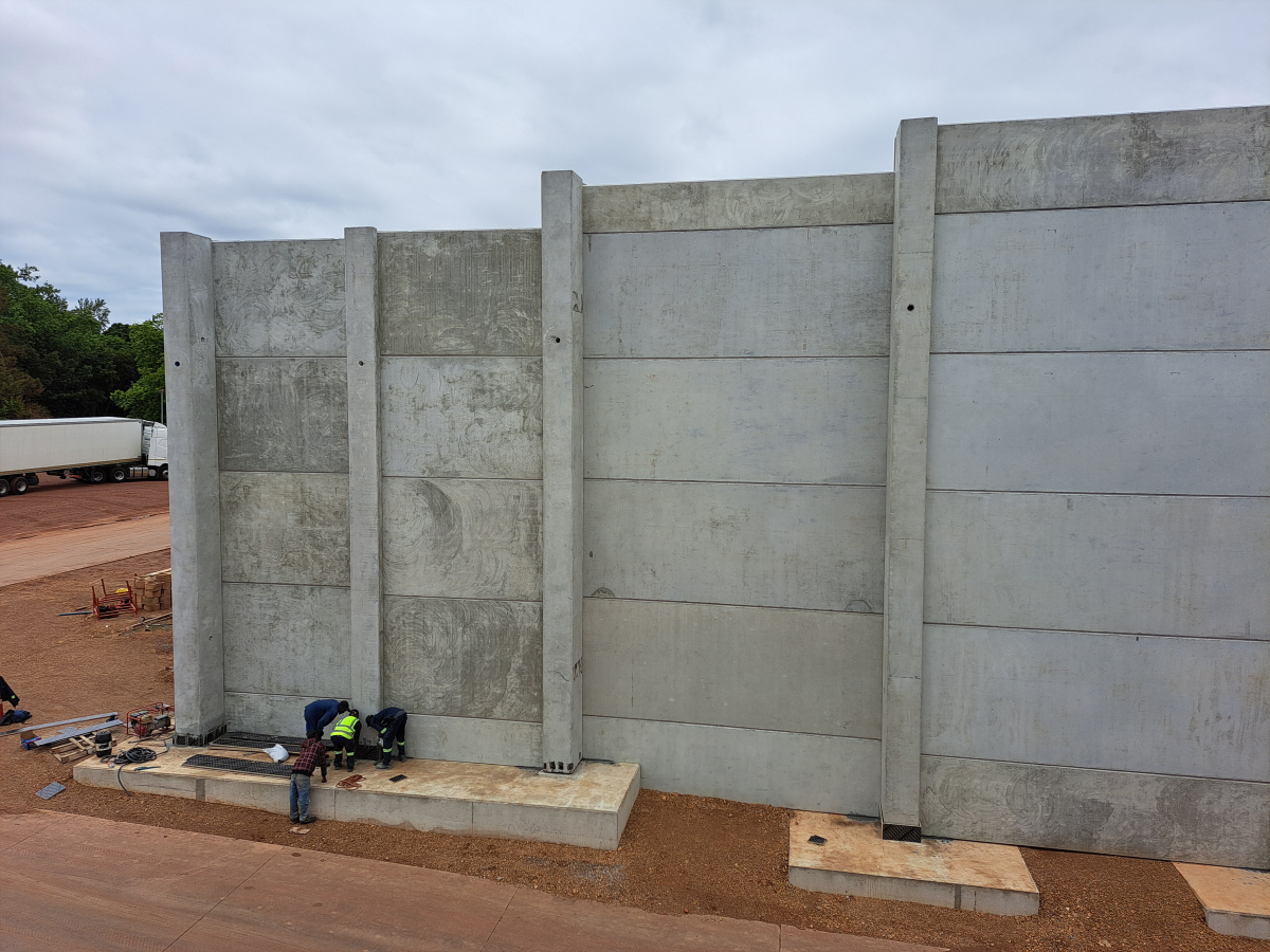
A massive firewall has been built between two Controlled Atmosphere (CA) storage facilities at Two-A-Day’s (TAD’s) apple and pear distribution centre in Grabouw, Western Cape. A hundred and thirtyfour metres long and rising to a height of 12.9m at its apex, the wall was built with mechanically anchored precast concrete columns and panels supplied by South African Concrete Manufacturers Association (CMA) member, Cape Concrete Works. TAD is one of the leading fruit growing, packing and marketing companies on the African continent, comprising more than 50 farms.
The wall was recommended by TAD’s insurance company, Swiss Re Corporate Solutions Africa Ltd,which regarded the two CA units as a single storage facility due to their close proximity. This assessment attracted a high insurance risk which was reduced after the wall had been built. The wall was designed by structural engineer, Herman Smith of Merlicon, to a four-hour fire rating and was installed by Cape Concrete together with Teemane Cranes using Peikko bolting systems. Main contractor, Francois Marais Construction, prepared the earthworks and cast the foundations for the columns and panels.
“The design was premised on a 125 page design brief submitted by Swiss Re and prepared by FM Global as the industry standard for Maximum Foreseeable Loss Limiting Factors, and it had to comply with international firewall requirements as well as local SANS regulations. Essentially, this meant that if one of the buildings caught fire the other would be protected for four hours,” said Smith. “The wall had to be robust enough to resist any impact loads produced by falling debris during a fire. Another design consideration was that if either building was destroyed by fire and not rebuilt the wall would require sufficient strength to handle a full frontal wind load.”
Extremely robust to withstand wind forces
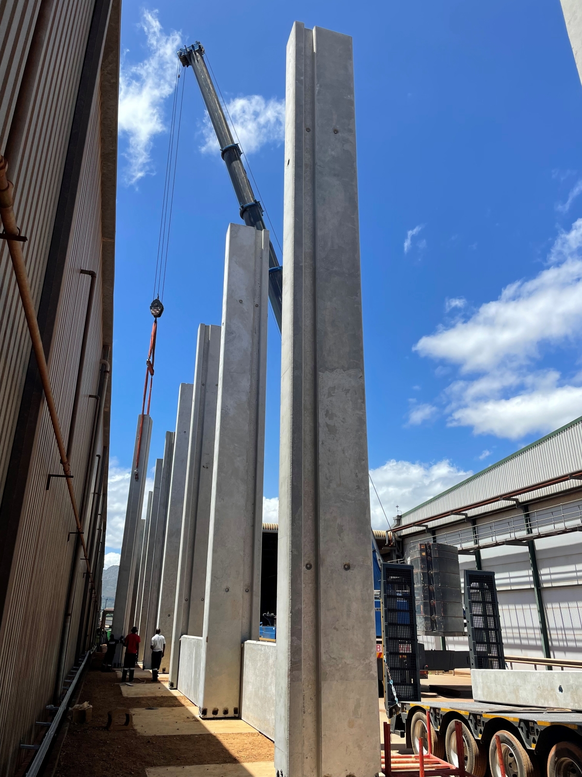
“And when the structure tops out at a height close on 13m it must be extremely robust to withstand wind forces which can be enormous. Had wind been the only design factor at TAD the columns could have been cast with high-density, high-strength concrete. But the higher a concrete mix’s density, the greater its explosive spalling potential when exposed to extreme heat. This is because high-density concrete has a low permeability which inhibits free water evaporation. Therefore we opted for a fairly low-density 30Mpa concrete for the columns and the panels, and this affected the dimensions of the columns and the reinforcement requirements.”
The columns are 600mm wide and 1.2m deep and vary in height between 10.5m and 12.9m. Fire and wind were the essential design drivers, giving the columns sufficient tensile strength to withstand a full frontal wind load on the one hand and enough concrete cover for fire protection on the other.
“When a column bends, the windward side is tensioned and the leeward side compressed. The tension force is resisted by the rebar which functions in tandem with the internal lever arm. And if the concrete cover over the rebar is increased as it was for this project, then the lever arm dimension is reduced. Therefore, to counter the reduced lever-arm effectiveness, rebar with a higher cross-sectional area had to be used to achieve the required tensile strength to resist the column moments. And we specified a concrete cover of 65mm with a sacrificial layer of steel mesh inserted just beneath the column faces to further inhibit spalling,” said Smith.
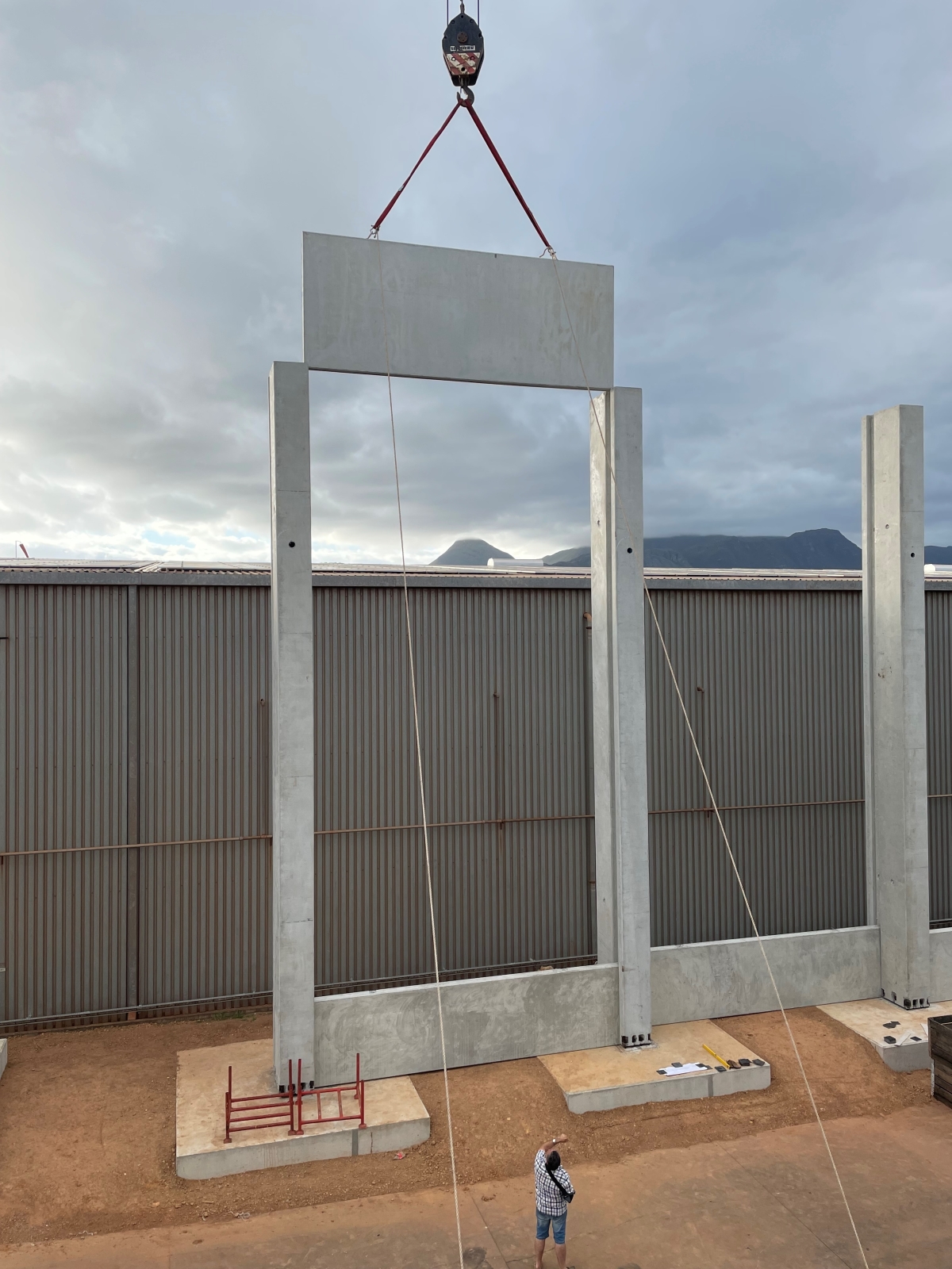
The main wall sections comprise concrete panels which were installed in a staggered configuration, because it stiffens the system and is one of the most efficient ways of designing a traditional boundary wall. Moreover, if we had placed the panels in a straight line, it would have meant that the installation grooves in the columns would have been opposite each other and that would have weakened the columns.
A 120 tonnes crane was used
The areas which will experience the greatest wind forces are located at the wall ends, whereas the lowest wind forces are at the wall’s mid-point. What’s more, wind-induced vortex forces can wrap around the wall ends and wrench them from the footings. To counter this scenario the wall ends had to be strengthened.
Half the space in which the wall was erected was confined to a narrow strip five metres wide between the one building and the canopy of the other. So instead of increasing the size of the columns, the number of columns was increased at the wall ends by reducing the centre-to-centre spacing of the columns. Additionally, three column footings were combined into one, thereby creating additional mass to resist overturning. This meant that the panel widths between these end columns were reduced from 6m to 3.54m. And the dimensions of these peripheral footings were 11m wide x 4m long x 700mm deep as opposed to the other footings which measured 4m x 3m x 700mm.
“All the panels were 180mm thick and we restricted the number of panel sizes to fourteen because fewer moulds meant cost savings and quicker installations. The latter was a crucial element because we needed to have the wall completed before the end of 2022 so that the insurance requirements could be adhered to. Most panels were 6m wide x 2,4m high and weighed close on seven tonnes. Initially they were only going to be 1.2m high but we decided to double this figure because we were using a 120 tonnes crane for installing the columns which weighed 24 tonnes apiece; this meant we could increase panel heights to 2.4m because even the largest panels weighed only 6.5 tonnes. Some of the panels had individual heights to accommodate the varying column heights but in the end we managed to reduce the number of panels from 242 to 132.”
The fire proofing requirement for the panels was not as stringent as it was for the columns, because only one face of each panel could be exposed to fire as opposed to three faces for the columns. The amount of vertical rebar used in the panels was equivalent to one percent of the concrete’s cross section. This was the amount required for the panels to be classified as a four-hour rated structural wall and not a plain concrete wall, as referred to by SANS 10100-1.
Anchor bolts from Peikko Gulf
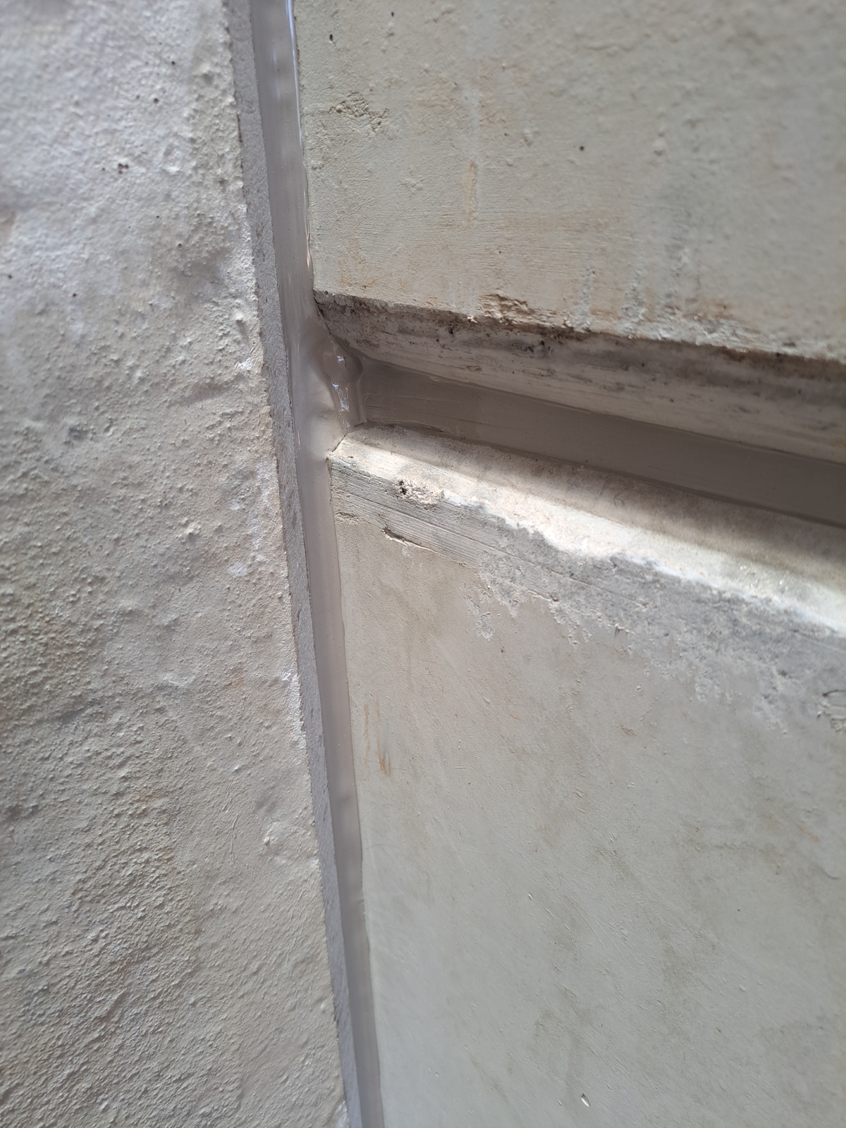
The panels were slotted into 200mm wide column grooves and were attached into each other with tongue and groove jointing. The bottom panels were all shimmed to ensure they were perfectly level. Low density, closed-cell expanded polyethylene was fixed to the vertical and horizontal joints as backing chords which were then sealed with a fireproof sealant supplied by Den Braven.
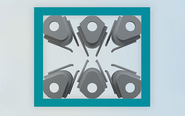
The columns were secured to the footings using Peikko bolted connections which made for fast and safe column installations. Peikko was very much involved in the design of the connections using its own bolting systems software to calculate the connection requirements. And Peikko anchor bolts and the column shoes were sourced from Peikko Gulf in the Middle East, one of 12 Peikko factories worldwide.
Cape Concrete cast two columns a day using steam curing for early strengths. It cast column shoes into the columns and manufactured anchor bolt templates based on drawings supplied by Peikko.
The templates were aligned on the footings by a surveyor using laser and gut lines. The columns were installed by lowering them onto levelling nuts attached to the anchor bolts. The levelling nuts were used for the vertical alignment of the columns, which once done, tightening nuts were used to secure the column shoes to the anchor bolts, thereby creating a permanent connection between the columns and the footings. The bases of the columns were grouted after the installations were complete to ensure a full connection and to protect the steel components from the elements.
Peikko project engineer, Winston Visser said that the number of bolted connections in each column depended on the moment forces applied to each column.
“Because wind forces diminish towards the centre of the wall, the number of bolted connections we used on each column decreased as we moved to towards the centre of the wall. Each of the outer columns were given 14 bolted connections whereas only six were required for the centre columns,” said Visser.
Safest precast wall system
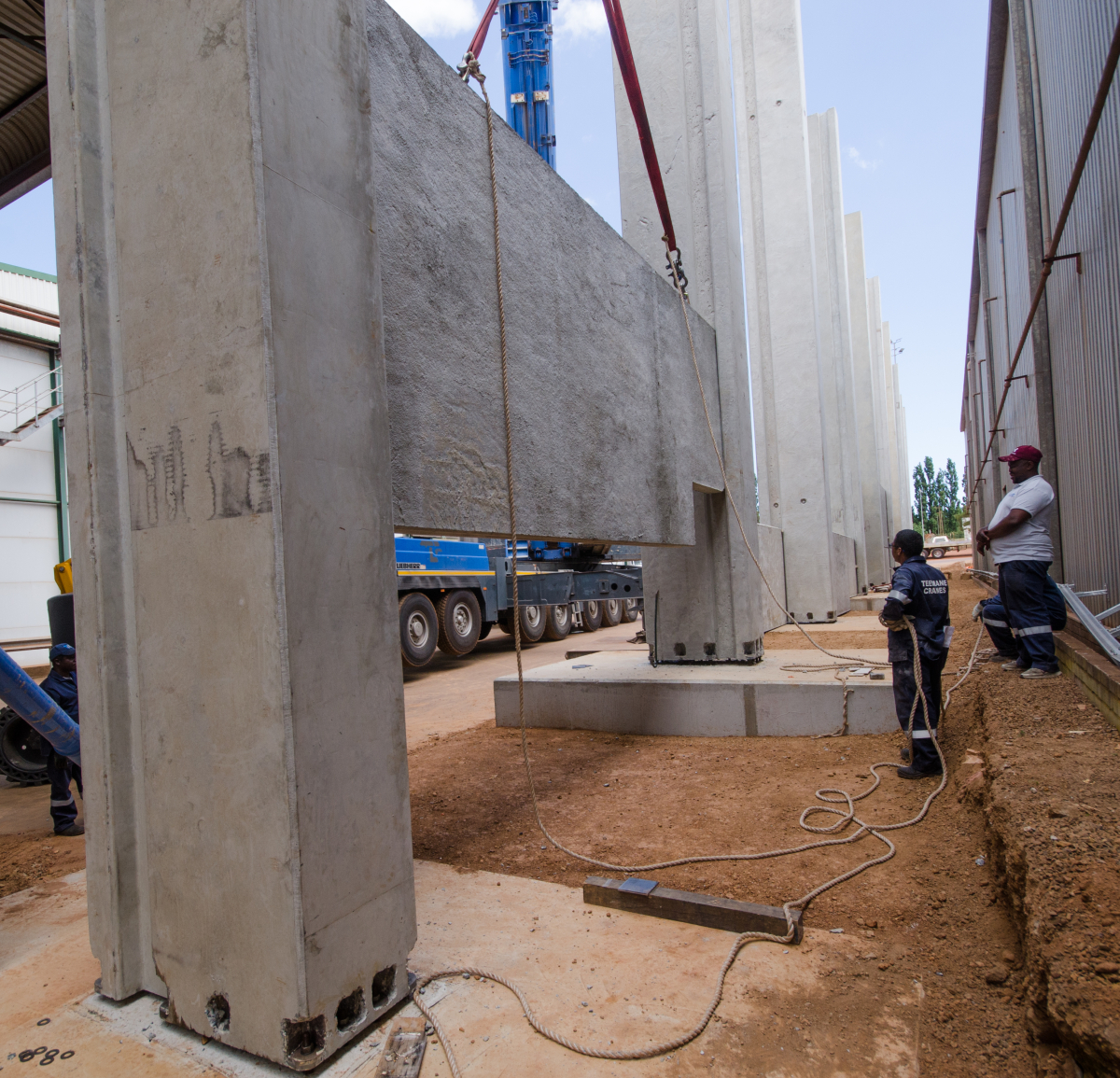
The installation of the columns and panels in the narrow five metre strip between the canopy and the adjacent building was complicated by the fact that the 120 tonnes mobile crane, which was parked on the strip, was prevented from offloading columns directly off the delivery trucks by the canopy immediately above the offloading area. Therefore the columns first had to be hoisted by two truck cranes parked under the canopy in the loading-yard. They were then shifted into the narrow construction strip where the mobile crane had access. A harness from the mobile crane was attached to the top end of the columns and the truck-crane harness at that end was disconnected. Once the columns had been lifted into a vertical position the harness of the second truck crane was disconnected. The columns were then lowered onto the footings and attached to the anchor bolts.
The installation of the panels in this confined section was undertaken in a similar fashion except that only one truck crane was used to lift them off the delivery trucks. The installation of the columns and panels in the open wall section was much simpler because the mobile crane had full freedom of movement to install them the normal way.
“The construction of the wall was further complicated by a fire water-line and an 11kVA electrical cable running under the strip where the wall was installed. The cable was rerouted and the water-line installed at a deeper level. Another design consideration was the canopy’s steel columns which were founded on concrete plinths. This affected the depth of the column footings because we did not want to undermine the canopy’s column bases.
“This precast wall system is by far the safest construction method because it precludes working on scaffolding at heights. Once the foundations were in place it only took 15 days to erect the wall. And one of the beauties of the Peikko bolting system is that only two workers, working on the ground, are required to install a column,” concluded Smith.
Text: David Beer
CONTACT
Cape Concrete Works
Wimbledon Rd., Blackheath 7580
Cape Town/South Africa
+27 21905 1200
Two-A-Day
Merlicon
François Marais Construction
Cape Concrete Works
Peikko South Africa
Teemane Cranes