State-of-the-art manhole production at Betonwerk Müller in Achern, Germany
South of Baden-Baden, backed by the Black Forest scenery, the headquarters of Betonwerk B. Müller has been situated since 1887. In 2006, the management decided to relocate the production facility because the ongoing residential development had moved very close to the original plant during the last few decades. Following a review of all existing options, the company decided to purchase a new plot of land in the industrial estate located only a few kilometers away. On this area covering over five hectares, a manhole base section production line was built that uses state-of-the-art technology. Including this new production site, Schlüsselbauer, the Austrian equipment supplier, has now installed more than a dozen of these Perfect systems across Europe.
Betonwerk Müller has been family-owned for five generations. Today, the business is being run by the two Managing Directors, Siegfried Müller and Joachim Strack. The company’s product range includes precast manholes, precast elements for rainwater drainage and use, and custom-made structures. Among other items, these include the dirt filtration unit. The company mainly serves the southwest of Germany. Rainwater utilization systems are also supplied to France.
The construction of the new plant on the newly acquired site is the largest investment the company has made during the last 100 years. Such a project requires sound planning and careful organization. This need is reflected in the schedule adopted for the project: The plot of land was purchased in 2006. In 2008, the factory building was constructed, the Perfect system set up and the mixing unit installed. This year, activities will focus on the completion of the external facilities and the office and staff building, and on the complete site relocation. Only a few employees are currently working in the new factory building while the major part of the workforce is still based at the old facility. Among other factors, this offers the advantage that all new technological features can be considered more efficiently prior to series production. Any delay that the new production process might bring about can be compensated more effectively by continuing to operate two sites. For this reason, no major production delays have occurred up to now.
Decision in favor of the Perfect system
The decision of Müller Schachttechnik in favor of a Perfect manhole base section production line has been considered very carefully. Although this product was known from trade shows and reports published in industry magazines, this type of process had been considered unnecessary for a long time since the business was always satisfied with the quality of the drain systems produced manually by the workforce, and held “skill and craftsmanship” in high regard. Yet the decision in favor of new construction questioned each and every production step and workflow implemented previously. This meant that the ultimate decision on how to produce the monolithic manhole base sections was easy: the quality of both manhole and drains is very high while the system also offers production flexibility. Such a monolithic manhole unit with absolutely even and dimensionally accurate surfaces appears to be the only correct answer when having to compete with plastic substitute materials.
In addition, the company intended to manufacture not only the usual DN 800/1000 dimensions but also DN 1200 and DN 1500. The equipment supplier developed its production line design further just to cater to this new aspect. These large formats require the adjustment of various processes and modules, such as a custom-designed handling system to cope with element loads of up to 8 t. The mix design was also aligned with the new product range and manufacturing method.
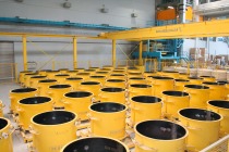
Crucial features of the precast plant are its cleanliness, adequate housekeeping and systematic workflows. For example, a uniform, consistent concept was also used for all pieces of equipment installed in the factory building. All plant and machinery parts, lifting systems etc. located in the building appear in blue and yellow to correspond to the corporate colors.
The factory gates are open to all customers; in addition, specifiers and relevant authorities are offered plant visits upon prior arrangement. This degree of transparency is to raise the awareness of the concrete plant and to generate an interest in Perfect manhole units. The business is well aware of the fact that civil engineering elements benefit not only from compliance with applicable standards but also from their visual and tactile appeal.
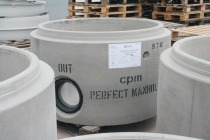
The new production process also permits the manufacture of manholes with connection diameters of up to 1,000 mm (Fig. 1). As a result, the new manhole range could be enlarged to include all usual types of pipes and connections. The awarding authorities served by the precast plant use manholes with drains at crown and at base level in their projects. The new production process ensures that all these requirements are met whilst maintaining a high quality standard.
Betonwerk Müller also produces manhole tops and covers to highest quality specifications. For example, manhole cones and rings are manufactured with integrated seals. The spigot end of manhole rings is produced very accurately using steel end rings and applying in-mold curing.
However, a minor percentage of the manholes will still be offered and supplied with tiled drains. This is due to the fact that there is still demand for this design. Moreover, there is no monolithic drain production process yet for larger manhole structures.
Fabrication of the semi-finished polystyrene element
Prior to concrete placement, each mold must be prepared with sleeve and drain as a negative form. The so-called negative form (or block-out element) of the drain forms a crucial part of this production process. At Betonwerk Müller, even a laser-controlled check of the semi-finished drain was included, using components provided by SL Laser.
In the “Perfect Control” program included in the system, each manhole to be produced is stored as an order with the associated bill of materials. This software also stores production-related information such as date of manufacture and product designation. On this basis, a product label can be provided and printed out. This label accompanies the element throughout the entire manufacturing process and is attached to the outside when it is finished. As a matter of course, this label is also a crucial part of the internal quality control and quality management systems (Fig. 2).
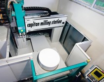
This software is used to retrieve the manhole to be produced and to display the required bill of materials listing the basic polystyrene (EPS) forms so that the employee is able to get all required parts from the warehouse. Once the forms of the relevant drains/nominal bores are available, the program defines the cutting work to be performed at the individual elements. For this purpose, the part to be cut is moved onto the 2D saw fitted with a gon scale visible on the table. Using a hot-wire cutting process, the standard forms for main and secondary drains are shortened to the required length.
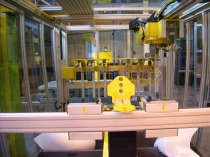
If the drain elements are placed on the laser projection board, the laser system already provides an option to check the correct routing of the drains, which significantly simplifies and automates the quality control process (Fig. 3). This ensures a high degree of accuracy. In the next work step, the individual drains must be joined very precisely. For this purpose, the numerically controlled 3D saw must be used (Fig. 4). Curved cutting wires are available for the various drain diameters to add the required curvilinear cut to the side inlets; in this process, the curved cutting wire corresponds to the diameter of the main drain. For this purpose, the polystyrene foam part can be adjusted in height while the tool height always remains the same in this saw unit.
A glue gun is used to bond the polystyrene parts for drain and inlet together.
In the next step, the base gradient is inserted. To do so, the drain combination is placed on a rotary plate that has a size equivalent to the manhole diameter. This method serves to insert all gradients required (the standard design is 1:20) in the cylindrical contact surface. The gradient is cut right into the pipe connection. Sawing off-cuts fall off without any further intervention after the 360° cut. The semi-finished part is then placed on the circular saw in order to accurately insert the outer radius (i.e. the manhole diameter) (Fig. 5).
In the last automated step of the process, the inlet parts saw is used (Fig. 6). At this point, the height-adjustable saw cuts the pipe connections so as to perfectly fit both drains and inlet. These cuts must also follow the radial mold shapes defined.
Each of these saw units is equipped with a small screen displaying the relevant parts and work steps, which serves as an additional means of checking.
The negative form has now been completely prefabricated. Employees attach the integrated seals and sleeves. In addition, a tape is attached to the glued drain and inlet joints from outside in order to avoid any treatment of any burrs or grooves at the finished manhole.
Casting of manholes
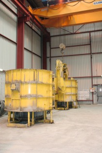
At this plant, the Perfect manhole base section molds have been installed in a stationary arrangement. Each mold has its defined position where it is filled with concrete.
Although this arrangement results in a lesser degree of automation, it makes the manufacture of special products easier.
The prefabricated negative drain consisting of polystyrene is put into the steel mold (Fig. 7). The contact edges are lined with a sealing strip in order to avoid the formation of burrs or grooves also at this stage. The application of wax to the polystyrene foam facilitates the removal of the negative form at a later stage. The manholes are produced in an upside-down arrangement.
The two spherical shells of the steel mold are closed, and the self-compacting concrete is cast. This SCC is ordered from the mixing unit positioned at one end of the line. From there, the concrete is transported into the factory building via a bucket conveyor. The mix is then fed into a bucket through an intermediate station (i.e. a feed hopper). Via a crane runway, each of the manhole base molds can be filled with concrete.
Manholes made of ultra-high performance concrete account for a certain part of the product range. The manholes consisting of UHPC are marked by red pigments added to the concrete. These premium elements are mainly used in sewage areas where the future, long-term use of urban neighborhoods is not certain yet, or where the high degree of contamination of the wastewater is
already known.
Demolding
Manholes can be demolded on the following production day. For this purpose, the two-part mold is opened (Fig. 8) and the manhole lifted from the steel mold. The manhole is inserted into the turning device, firmly held in place by this unit and turned by 180° (Fig. 9). This means that the manholes are put down in accordance with their assembly position (i.e. no longer in an upside-down position). At this stage, the drain mold is removed (Fig. 10). The resulting styrofoam residues are collected and re-used. Following a recycling step, this material can be fed back into the process at a later stage.
On the conveyor running through a factory door, the manhole is then transported to an area outside the building. In this outside area and in the storage facility, all precast concrete elements are handled with forklift trucks.
Outlook
This investment puts Müller Schachttechnik in a perfect position to be prepared for future challenges and to meet all customer requirements. The Perfect production process provides the company with the required planning flexibility to be utilized to the benefit of its customers whilst optimally supporting hydraulic performance by manufacturing premium precast elements with a monolithic structure and smooth surface.
Andrea Janzen

