Adhesive shear strength and sliding friction
of mineral foam insulated sandwich facades
There is currently a lack of basic knowledge regarding the structural behavior of ultra-light mineral foams used in precast sandwich walls. To close this gap, this article discusses and analyzes experimental tests carried out to determine the adhesive shear strength and sliding friction between ultra-light mineral foam and standard concrete.
Concrete sandwich wall panels prefabricated at the precast plant have been used as external wall systems for many years and have proved to be a viable solution in construction practice. They provide a wide range of design options while meeting the increasingly demanding requirements for thermal insulation. The major share of currently used insulation materials is petroleum-based. The firm bond between the organic insulation material and the mineral-based concrete results in a composite that is difficult to dispose of, thus preventing the subsequent recycling of concrete sandwich walls.
To establish closed material loops, organic insulation materials must be replaced by purely mineral materials such as ultra-light mineral foam. However, there is currently a lack of basic knowledge regarding the structural behavior of such foams in precast sandwich walls. To close this gap, this article discusses and analyzes experimental tests carried out to determine the adhesive shear strength and sliding friction between ultra-light mineral foam and standard concrete.
1. Background and objective
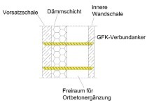
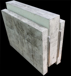
Precast sandwich walls are triple-layer reinforced-concrete wall panels composed of a facing panel, a load-bearing panel and an insulation layer installed at the precast plant [1] (see Fig. 1). The facing panel is self-supporting, acts as an architectural design element and fulfils the function of protecting the insulation material from weather impact. Discrete connectors fix the facing panel to the load-bearing panel via the insulation layer. Bar-shaped glass-fiber-reinforced plastic connectors are the most commonly used option. The load-bearing panel consists of reinforced concrete and fulfils the load transfer function.
Most commonly used insulation materials include expanded polystyrene (EPS), extruded polystyrene (XPS) and polyurethane-based materials (PUR) [1]. The process of producing sandwich walls at the precast plant with porous or profiled insulation material surfaces usually results in a firm bond between the organic insulation material and the mineral-based concrete used for the facing and load-bearing panels. This is why crushing of the precast sandwich walls at the end of their life cycle creates composite waste that prevents recycling within closed material loops [2].
Not only is transforming the existing linear approach to production, use and disposal into a resource-efficient circular economy an overarching objective of the European Union [3] and the United Nations [4]; it is also imperative for economic reasons owing to price increases for relevant construction materials [5]. One possible solution is to replace organic insulation materials by ultra-light mineral foams, which avoids difficult-to-separate composite waste while providing the potential of creating closed material loops. Latest advances in material optimization in terms of the stability and thermal conductivity of ultra-light mineral foams increasingly suggest that the use of such foams as insulation materials in precast sandwich walls could be a viable alternative [6].
Ultra-light mineral foam is non-combustible and self-curing. In its fresh state, it is pumpable and freely formable so that it is no longer necessary to cut insulation panels to size in the production process. Mineral foams with a bulk density of r ≤ 160 kg/m³ appear to be particularly interesting due to their low thermal conductivity. Foams with a bulk density under 120 kg/m³ provide relatively low strength levels and are thus not suitable for producing precast sandwich walls. Reference [7] contains an overview of the material characteristics and methods of producing mineral foams.
2. Actions on the thermal insulation material in concrete sandwich walls
Over their life cycle, the bar-shaped connectors and the insulation material of precast sandwich walls are essentially exposed to the dead load of the facing panel, wind loads and temperature variations, which result in actions on the connector and insulation material in the shear plane. Fig. 2 (left) illustrates the relationship between the force acting in the shear plane Q and the differential displacement of the two concrete panels u. The load-bearing behavior of the connector and the insulation material is captured in three basic structural models, namely the shear resistance of the insulation, the flexural resistance of the connector, and the combined bearing capacity of the system created by the connector and the insulation material in accordance with [8], [9]. Fig. 2 (right) illustrates these models.
Load-bearing component 1 results from the shear resistance of the insulation and acts until the adhesive shear strength between the thermal insulation material and the concrete ThD or the shear strength of the insulation material TsD is exceeded. The load-deflection curve of load-bearing component 1 can be described by the shear modulus of the insulation GD, the connector grid AVM, the insulation thickness hD and the differential displacement of the two concrete panels u (see (Eq. 1)Q1 = GD * AVM / hD * u
The connector transfers a certain portion of the force in the shear plane Q through bending (load-bearing component 2) [9]. The load-deflection curve of a bar-shaped connector can be described by the analytical relationship for a bilaterally restrained bar with the diameter shown in (Eq. 2). In this formula, EVM represents the connector’s bending stiffness while hVM is the effective bearing width of the connector according to (Eq. 3), and hD is the thickness of the insulation layer.
Q2 = 12*Evm * lVM / hvm³ * u
hVM = hD +2 *0,5 * OVM
If the adhesive shear strength between the insulating material and the concrete ThD is exceeded, the differential displacement u causes the facing panel to be pulled towards the load-bearing panel. This movement creates a frictional force between the insulation material and the concrete Q3 (load-bearing component 3), which can be described by (Eq. 4). In this formula, m is the coefficient of sliding friction between the insulating material and the concrete while ED is the modulus of elasticity of the insulating material.
Q3 = m * ED * Avm / ( 2 * hD * hvm * ) * u²
Characteristic values for the load-bearing behavior in compression are already available for ultra-light mineral foams [6, 10, 11]. However, it is not yet possible to consider the above load-bearing components because of the absence of characteristic values for the coefficient of sliding friction m and the adhesive shear strength between the ultra-light mineral foam and the concrete. This is why this article discusses experimental tests and their results regarding the sliding friction m and adhesive shear strength ThD between the two materials.
3. Experimental testing of friction and adhesive shear strength
Experimental tests were performed on three different ultra-light mineral foams with bulk densities between ρ = 120 kg/m³ and ρ = 160 kg/m³ in order to determine the coefficient of sliding friction m and the adhesive shear strength ThD between the ultra-light mineral foam and the concrete. Table 1 includes the essential physical and mechanical characteristics of the tested ultra-light mineral foams.
The test specimens for the experimental investigations consisted of two geometrically identical layers of different materials with a footprint of 100 × 210 mm. Each layer was 45 mm high; the lower half consisted of standard C50/60 concrete while the upper half was an ultra-light mineral foam in accordance with Table 1. Pouring of the normal concrete against the mineral foam created an adhesive bond between the two layers. A phenolic plywood panel was glued onto the top side of the ultra-light mineral foam to ensure uniform load application.
Table 2 includes the testing program for determining the coefficient of sliding friction m and the adhesive shear strength ThD. These tests involved three different ultra-light foams (MF1 to MF3), and the vertical force FV acting on the bond joint was varied from 0.5 kN to 1.5 kN.
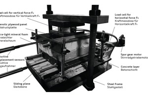
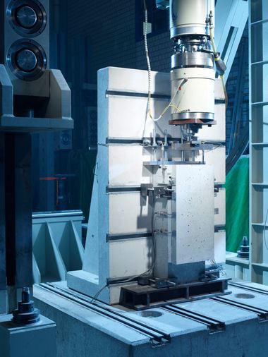
The setup described in [15] and shown in Fig. 3 was used for the experimental tests. The test rig included a steel frame to which the specimen was attached, with the bottom (concrete) layer being flexible in the horizontal direction and the top (ultra-light mineral foam) layer firmly fixed to the plywood panel.
A connecting rod linked a spur gear motor to the concrete layer. During the test, this motor moved the bottom (concrete) layer against the top (ultra-light mineral foam) layer. A load cell measured the horizontal force Fh required for this purpose. Prior to commencing the test, a vertical (compressive) force FV was applied to the specimen through clamping. Again, this force was captured by a load cell. In addition, inductive displacement sensors measured the horizontal displacement of the two layers during the test.
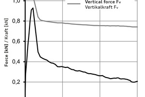
Fig. 4 shows the load-displacement diagram of test MF1-C50/60-1.0-1 separately for the horizontal force Fh and the vertical force Fv. The curve representing the horizontal force Fh follows a degressive pattern until reaching the maximum horizontal force Fh,max at a displacement of 1.6 mm. At this point, the adhesive shear strength ThD between the ultra-light mineral foam and the concrete is exceeded. Thereafter, the horizontal force Fh declines to about 0.45 kN, followed by a quasilinear curve progression. The value of the vertical force Fv remains at an almost constant level until reaching the adhesive shear strength ThD. Upon exceeding it, the Fv value declines from about 1.05 kN to 0.8 kN. The vertical force Fv also declines, but this decrease is less pronounced compared to the horizontal force Fh.
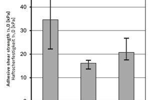
We determine the adhesive shear strength ThD by means of (Eq. 5), dividing the maximum horizontal force Fh,max by the specimen footprint of A = 21,000 mm². Fig. 5 shows the mean values of the experimentally determined adhesive shear strengths ThD of the three tested ultra-light mineral foams, namely ThD = 34.6 kPa for MF1, ThD = 16.2 kPa for MF2, and = 20.8 kPa for MF3.
ThD = Fh,max / A
After exceeding the adhesive shear strength ThD, sliding friction occurs owing to the relative displacement of the surfaces. We use the basic friction formula shown in (Eq. 6) to calculate the coefficient of sliding friction m by dividing the horizontal force Fh by the vertical force Fv.
m = Fh / Fv
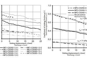
Fig. 6 (left) shows the experimentally determined coefficients of sliding friction over the sliding displacement s after exceeding the adhesive shear strength ThD for the three ultra-light mineral foams. We find that the coefficient of sliding friction m declines in a quasilinear pattern over the sliding displacement s in all tests. At the same time, it reveals a major variation within the individual test series, analogously to the adhesive shear strength ThD. The values of the coefficient of sliding friction m at s = 0 mm range from m = 0.14 in test MF2-C50/60-1,5-1 to m = 0.8 in test MF2-C50/60-0,5-1. Over a sliding displacement of s = 25 mm, the coefficient of sliding friction shows a mean decline of 42%.
Fig. 6 (right) shows the influence of the vertical force on the coefficient of sliding friction m. The normal stresses perpendicular to the joint sN derived from the vertical force Fv amount to σN = 24 kPa, σN = 47 kPa, and σN = 71 kPa. Thus, the maximum normal stress lies within the range of the compressive strength σ10 of the ultra-light mineral foam MF2 (see Table 1). Fig. 6 (left) indicates that the minimum and maximum normal stresses in the joint constitute the limiting curves.
The empirical (Eq. 7) is derived from the test results. In so doing, the normal stress in the joint σN and sliding displacement s are inserted in the equation as linear parameters. Fig. 6 (right) shows the recalculation of the test results using (Eq.7).
μ (σN ,s) = (-0,0152 + 0,0002 * σN ) * s + 1,1365 – 0,0142 * σN
Additional results of experimental tests are necessary to validate (Eq. 7) owing to the small number of performed tests and major variations of results. However, this equation indicates the identified key parameters influencing the coefficient of sliding friction μ, i.e. the sliding displacement s and the normal stresses in the joint σN.
4. Summary and conclusion
Concrete sandwich walls have been used as external wall systems for many years and have proved to be a viable solution in construction practice. Currently used petroleum-based insulation materials create a firm bond to the concrete and, consequently, composite waste that prevents the transition from the existing linear production pattern to a resource-efficient circular economy. Replacing petroleum-based insulation materials with ultra-light mineral foam makes it possible to produce purely mineral concrete sandwich walls and to establish closed material loops. Characteristic values of the adhesive shear strength between mineral foam and concrete as well as friction values that would permit the design of the sandwich wall core using ultra-light mineral foam as the insulation material are currently lacking. To close this gap, this article discussed and analyzed experimental tests carried out to determine the adhesive bond and sliding friction between ultra-light mineral foam and standard concrete.
For this purpose, three different mineral foams with bulk densities between r = 120 kg/m³ and r = 160 kg/m³ were considered. In the tests, adhesive shear strengths ranged from ThD = 13.7 kPa to ThD = 44.2 kPa, with the results revealing significant variations. The coefficient of sliding friction μ showed a quasilinear decline over the sliding displacement s. At the same time, the normal stress perpendicular to the joint σN was identified as a key parameter influencing the coefficient of sliding friction μ, for which values between μ = 0.79 and μ = 0.06 were derived from the test results.
In this article, we derived an empirical equation for determining the coefficient of sliding friction μ as a function of the sliding displacement s and the normal stress perpendicular to the joint σN in order to recalculate the results of the experimental investigations. The small number of performed tests and major variations of results mean that we were only able to identify a trend and to indicate basic mechanisms. This is why additional experimental tests are necessary with particular emphasis on investigating the wear of ultra-light mineral foam subject to cyclic deformation.
Acknowledgements
The authors thank the German Federal Environmental Foundation (DBU) for their financial support, as well as Technische Universität Darmstadt and Wilhelm Röser Söhne GmbH & Co. KG, Zuber Beton GmbH and Südhessische Wertstoffrückgewinnungs GmbH for the collaboration within the |2CO2|sandwich research project (AZ 34088).
REFERENCES/LITERATUR

![Fig. 2: Schematic load-bearing behavior of the thermal insulation material and the bar-shaped connector in shear, taken from [8]](https://www.bft-international.com/imgs/1/7/2/4/9/8/6/tok_484fafba84135085baefc3e458b882ba/w300_h200_x600_y173_HA_1124_Fig.2_Abbildung_2-3ec298ac243824e0.jpeg)
