Compressive strength classes and performance classes of ultra-high-performance concrete (2)
At present, a national technical approval or an approval on a case-by-case basis is required for structural applications of concretes >C100/115 as well as steel-fiber-reinforced concretes >C50/60. This holds true likewise to the application of ultra-high-performance concrete (UHPC), which is not yet regulated in Germany. Please read the second part here (References, vitae see part 1).
3 Classification of UHPFRC in tension
3.1 Parameters and test method
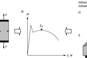
The axial post-cracking tensile strength (notation: fcft) is the most important material parameter of ultra-high-performance fiber-reinforced concrete (UHPFRC) in tension. It is defined as the maximum nominal concrete tensile stress under axial tension which can be carried by the action of fibers in the cracked state. It therefore corresponds to the maximum value of the stress-crack opening or stress-strain curve in the post-cracking range (Fig. 8d).
Several methods have become established for the determination of the axial post-cracking tensile strength of steel fiber reinforced concrete. The axial post-cracking tensile strength is obtained directly in tensile tests conducted on unnotched (Fig. 8a), dog-bone-shaped (Fig. 8b) or notched specimens (Fig. 8c) (so-called direct methods). The performance of such tests is however elaborate and prone to errors [18]. Therefore, bending tests on beams, less commonly also round panel tests [19] or splitting tensile tests [20], are preferred in building materials testing (so-called indirect methods).
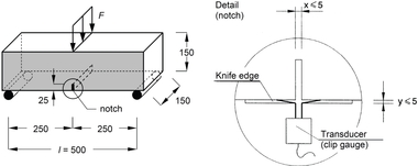
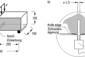
Bending tests on beams are either carried out as 3-point tests on notched beams (e. g., according to DIN EN 14651 [21]; Fig. 8e) or as 4-point tests on unnotched beams (e. g. according to DAfStb Guideline „Steel Fibre Reinforced Concrete“ [4]; Fig. 8f). The 4-point test has proved to be disadvantageous, in particular for higher fiber volume fraction because the course of the load-deflection curve essentially depends on the arbitrary crack pattern and the specific location of the decisive failure crack owing to the missing notch. Fig. 9 is an example of load-deflection curves determined in 3-point tests (Fig. 9a) and 4-point tests (Fig. 9b) on flexural beams made of the same UHPFRC mixture. The courses of the load-deflection curves of the 4-point tests vary more than those of the 3-point tests. Due to the multiple cracking of the unnotched beams, which became manifested in the inclined branch between a deflection of about 0.5 mm and reaching the ultimate load, crack width and midspan deflection can no longer be correlated in the 4-point test. Therefore, the draft of the DAfStb Guideline „Ultra-High-Performance concrete“ establishes the 3-point test according to DIN EN 14651 (Fig. 10a) as test method.
In this test, the load F and the crack mouth opening displacement (CMOD; Fig. 10b) or the midspan deflection of the beam d are measured. From the loads Fj acting at CMOD1 = 0.5 mm, CMOD2 = 1.5 mm, CMOD3 = 2.5 mm and CMOD4 = 3.5 mm (or alternatively d1 = 0.47 mm, d2 = 1.32 mm, d3 = 2.17 mm and d4 = 3.02 mm) so-called residual flexural tensile strengths fR,j are calculated assuming a linear-elastic behavior of the beam. Afterwards, these residual flexural tensile strengths must be converted into axial post-cracking tensile strengths taking into account the actual non-linear stress distribution at the cracked cross-section.
As part of the DAfStb V 497 research project, comprehensive tests were conducted [22, 23] in order to specify determinations for the conversion of the residual flexural tensile strength into the axial post-cracking tensile strength of UHPFRC.
3.2 Experimental investigations regarding the conversion of the residual flexural tensile strength into the axial post-cracking tensile strength
The test program (Table 3) comprised seven series of UHPFRC, varying the maximum aggregate size (Dmax = 0.5 mm, 3 mm and 8 mm), the fiber geometry (lf/ff = 9 mm/0.175 mm and 17 mm/0.20 mm) and the fiber volume fraction (ρf = 0.5 %, 1.0 % and 2.5 %). Series 2A is a repetition of Series 2 and served to verify the results. The mean compressive strength of the individual series was determined by means of cubes with d = 100 mm and was between 160 and 189 MPa.
Each test series comprised 6 beams with l/b/h = 550 mm/150 mm/150 mm, which were examined in 3-point tests according to DIN EN 14651 (Fig. 10), as well as 24 tensile specimens, which were examined in axial tensile tests (Fig. 11b). In order to ensure that the flexural beams and the tensile test specimens show comparable tensile characteristics, the tensile test specimens were cut out of four additional beams each with l/b/h = 550 mm/150 mm/150 mm (Fig. 11a). The beam molds were filled from one front end of the formwork. The test specimens were covered with foil immediately after concrete pouring. They were demolded after 24 hours, stored under water until the 28th day, and then stored under indoor climate conditions until being tested.
In order to force the failure of the tensile specimens at the same cross-section as with the notched beams (center of the specimen), an epoxy resin adhesive was used to glue two steel plates each on two opposite lateral faces of the tensile specimens leaving a gap („notch“) of approx. 2 mm in length at the center of the tensile specimen (predetermined breaking point). The tensile specimens strengthened in this way were clamped directly in the clamping device of the testing machine especially adjusted for this purpose. Experimental set-up and instrumentation are described in detail in [22, 23].
3.3 Results of the 3-point bending tests and the axial tensile tests
The evaluation of the 3-point bending tests was performed by means of load-deflection curves and residual flexural tensile strengths fR,j. Fig. 9a and Fig. 12 are examples for the load-deflection curves obtained in Series 1, 3 and 4, clearly indicating the influence of the fiber length on the course of the curve and the deflection at reaching the maximum load. The residual flexural tensile strengths fR,j of the beams were determined according to [21] on the basis of the midspan deflections d1 up to d4 given in section 3.1. The axial post-cracking tensile strength was determined from the maximum load in the post-cracking range measured in the axial tensile tests (Fig. 11b) divided by the actual cross-sectional area of the “notched” cross-section.
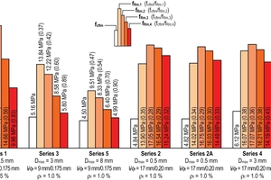
The results are represented in Fig. 13 in the form of a column chart. The test series are arranged according to the length of the fibers used in the respective series (Series 1, 3 and 5: short fibers; Series 2, 2A, 4 and 6: long fibers) in order to illustrate the corresponding systematics. The height of the colored columns represents the mean values of the residual flexural tensile strengths fRm,j at the deflections dj (and the corresponding CMODj, respectively). The height of the white column corresponds to the mean value of the axial post-cracking tensile strength fcftm. The ratios between the mean axial post-cracking tensile strength and the various mean residual flexural tensile strengths of the same series are given in parentheses.
Since the force acting on the beam decreases faster with increasing midspan deflection (opening of the flexural crack) in case of short fibers than in case of long fibers (cf. Fig. 12), an evaluation for the midspan deflections d2 to d4 for the series using short and long fibers, respectively, results in quite different ratios fcftm/fRm,j, which are not suitable for establishing a general conversion factor between residual flexural tensile strength and axial post-cracking tensile strength. Whereas an evaluation with small midspan deflection (d1 = 0.47 mm and CMOD1 = 0.5 mm, respectively), i. e. at the rising branch of the load-deflection curve or close to the maximum load, results in similar ratios for 6 of the 7 series of 0.34 to 0.41. Series 5 provides an outlier with fcftm/fRm,1 = 0.47. In principle, the ratio fcftm/fRm,1 seems to be most appropriate for a simplified conversion between residual flexural tensile strength and axial post-cracking tensile strength. Disregarding the extraordinarily high value obtained in Series 5, the mean ratio fcftm/fRm,1 is 0.37.
3.4 Conclusions for the classification of UHPFRC in tension
The draft of the DAfStb Guideline „Ultra-High-Performance Concrete“ provides performance classes for the classification of UHPFRC. The performance classes are marked by the L symbol, followed by the so-called basic value of the axial post-cracking tensile strength fcft0 given in MPa. In order to classify UHPFRC into a performance class, the characteristic value of the residual flexural tensile strength determined in 3-point tests according to DIN EN 14651 for a midspan deflection of d1 = 0.47 mm (and CMOD1 = 0.5 mm, respectively) is simplifying converted into an axial post-cracking tensile strength, using the coefficient 0.37 from section 3.3. This results, for example, in a characteristic value of the residual flexural tensile strength of 13.5 MPa that has to be verified in a 3-point test in case of performance class L5.0 (fcft0 = 5.0 MPa).
Since the axial post-cracking tensile strength of UHPFRC is significantly affected by the orientation of the fibers, the basic value of the axial post-cracking tensile strength has to be adjusted in such cases where the specific fiber orientation in the structural member differs from that of the specimen used in the building materials test, owing to different geometry, production method or type of loading. For this purpose, the draft of the DAfStb Guideline „Ultra-High-Performance Concrete“ defines coefficients, taking into account the ratio between the mean fiber orientation in the control section of a structural member and the mean fiber orientation at the cracked cross-section of the beam tested in the 3-point test.
4 Summary
The DAfStb Guideline „Ultra-High-Performance Concrete“ will considerably increase the spectrum of structural concretes compared to DIN EN 206 and DIN EN 1992-1-1. To minimize the brittleness at compressive failure and to increase the robustness of the load-bearing structure, the use of steel fibers for structures made of UHPC is mandatory. Compressive strength and axial post-cracking tensile strength are the key mechanical parameters of ultra-high-performance fiber-reinforced concrete (UHPFRC). These parameters are used for the classification into „compressive strength classes“ and into „performance classes“.
Not only the fiber volume fraction but also the fiber orientation has a significant influence on the mechanical parameters. The fiber orientation essentially depends on the geometry of the structural member and the production method, as the fibers preferably are aligned in the flow direction of the fresh concrete. Within a concrete volume, the fiber orientation can locally differ substantially. Then, UHPFRC shows a different load-bearing behavior in tension as well as in compression, depending on the loading direction. The anisotropy is more pronounced with increasing fiber volume fraction.
Therefore, the compressive strength of test specimens not only depends on the slenderness and size, but also on the fiber volume fraction and the fiber orientation with regard to the compression direction. Moreover, flatness and plane-parallelism of the loaded surfaces have a greater influence on the results of compressive strength tests on UHPFRC than in the case of normal-strength and high-strength concrete. The highest compressive strengths with low scattering are obtained by grinding even the loaded surfaces of the cubes.
The tensile load-bearing behavior of the cracked UHPFRC is characterized by means of the axial post-cracking tensile strength. Its basic value is not directly determined but by means of a bending test. This test is performed as a 3-point test using a notched beam according to DIN EN 14651. Taking into account the non-linear stress distribution occurring in the cracked state, the basic value of the axial post-cracking tensile strength is determined from the residual flexural tensile strength at small midspan deflection of the beam. This basic value is used for the classification of the UHPFRC into a „performance class“. In the design process, deviating fiber orientations in structural members will be taken into account by correction factors.
5 Acknowledgement
The investigations presented were obtained as part of the DAfStb V 497 and V 501 research projects. The authors are grateful to the German Committee for Structural Concrete (DAfStb) as well as the companies NV Bekaert SA Building Products and KrampeHarex GmbH & Co. KG for the financial and material support.

![Fig. 9: Load-deflection curves of 3-point tests acc. to DIN EN 14651 (left) and of 4-point tests acc. to DAfStb Guideline “Steel Fibre Reinforced Concrete” (right) for UHPFRC of Series 1 from [23] (see chapter 3.2)](https://www.bft-international.com/imgs/1/6/0/1/3/6/8/tok_e1dd081951bf86f4210c264630cc868b/w300_h200_x600_y233_HA_1064_Fig.09_Bild_9_NEU-4f2005c295b3619d.jpeg)
![Fig. 11: Direct tensile test: a) geometry and location of the tensile specimens cut from beams (gray: side from which the mould was filled; dimensions in mm); b) tensile specimen with instrumentation [23]](https://www.bft-international.com/imgs/1/6/0/1/3/6/8/tok_4d1818740ed44b7392f83f6bb8bb952d/w300_h200_x600_y262_HA_1064_Fig.11_Bild_11-5e21e14c24a3a262.jpeg)
![Fig. 12: Load-deflection curves of 3-point tests acc. to DIN EN 14651 for UHPFRC of Series 3 (left) and 4 (right) from [23]](https://www.bft-international.com/imgs/1/6/0/1/3/6/8/tok_eb57723513f9fc1a91864bbd89c3ee09/w300_h200_x600_y232_HA_1064_Fig.12_Bild_12_NEU-e9bb9904b31c3cf4.jpeg)
