Pouring determines the properties of structural elements
Concrete is a multipurpose construction material which can be tailored to have numerous different properties. In most cases, it is optimized with respect to the hardened concrete properties, that is, in terms of the requirements placed on the completed structural element. Pouring, compaction and the consistency chosen to match these processes are rarely planned but, in most cases, left to the concreting crew of the subcontractor.
As regards fresh concrete behavior, robust mixes can be produced that will not segregate even in case of extended vibration. They do not have a sufficiently high cement paste content for pumped concretes to show a significant excess of cement paste. These are concretes in consistency classes F2 and F3. They are plastic to soft, that is, they will “flow” to a negligible extent only and require intensive compaction.
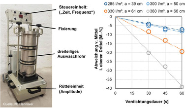
Concretes in consistency classes F4 and, in particular, F5 or F6 usually have an excessively high cement paste content; the aggregate particles “float” in the excess cement paste. The high amount of cement paste is deliberately tailored to have a sticky consistency so that the aggregate particles adhere to the cement paste and there is virtually no settling of the aggregate particles as a result. If such concretes are discharged from a greater height, driven horizontally or vibrated intensively, the internal stickiness (friction) is temporarily neutralized by the movement and the aggregate particles sink to the bottom in the excess cement paste. The same happens if, for example, unauthorized water is added as this will significantly reduce the previously defined degree of stickiness. It allows an aggregate-free layer of up to 1.5 cm in height to form on top of a 25 cm thick horizontal concrete slab (Fig.). In the case of walls, there may even be aggregate-free layers of up to 20 cm in height in the upper wall section. The aggregate-free layer has an increased content of hardened cement paste and shrinks about twice the amount of the design concrete. This leads to map cracking in horizontal slabs and to vertical cracks in walls, which end at the depth at which sufficient coarse aggregate is again present. This can be easily checked by means of a fresh-concrete finger test which involves simply probing for the depth of the first aggregate particles. To enable proper pouring, walls require filling openings to be provided at intervals of 2-3 m and a vibrating unit every 45 cm. In order to prevent segregation during discharge by gravity, the concrete should be transported to just above the pouring site in pipes (or by means of a hose) and should not be spread laterally by more than approx. 1.5 m during pouring. Close-meshed reinforcement may additionally “screen” the coarse aggregate. Appropriate spacing of the reinforcement must therefore be included in the design (Table 1), as must paths for pouring and vibrator insertion (Table 2), which then determines the largest maximum particle size. The “miracle cure” applied in building practice to select 8 mm as the maximum particle size produces concretes with an increased water or cement content due to the larger aggregate surface to be bonded. In numbers, this equals approx. 10% more hydration heat and approx. 40% higher shrinkage compared to a maximum particle size of 16 mm or 32 mm. In addition, pouring pipes or pumping hoses of smaller diameter need to be kept on the construction site for reduction purposes. The concreting crew must have been instructed to pour the concrete correctly and in uniform layers of approx. 50 cm in thickness. At the same time, the vibrator chosen should not be too large to avoid over-compaction. For a 30-cm wall, a 45-mm vibrator should be used at immersion intervals of 45 cm.
lichter Abstand max. zulässiges
Bewehrung bw,i Größtkorn
< 12 cm unzulässig
12 bis < 14 cm 8 mm
14 bis < 18 cm 16 mm
≥ 18 cm 32 mm
Table 1: Required reinforcement spacing
Tab. 1: Notwendiger Bewehrungsabstand
geplante Pumpenschlauch Größtkorn
Öffnung Nennweite außen
cm x cm mm mm mm
< 12 x 12 unzulässig
≥ 12 x 12 65 80 8
≥ 14 x 14 80 100 16
≥ 18 x 18 125 150 32
Table 2: Required filling openings at intervals of 2-3 m
Tab. 2: Notwendige Einfüllöffnungen alle 2-3 m

