Power absorption and experimental results of concrete twin shaft mixers
This paper focuses on twin-shaft concrete mixers and on the mixing phases in order to study the influence of the filling level on the power consumption. The analysis is predominantly experimental, and the tests are presented to study the mechanical behavior of twin-shaft mixers, when the filling level varies in a realistic production range.
In the concrete mixers’ technology, the mixing process can be performed by different types of mixers [1-9], whose behavior is influenced by the mixer geometry and the operating conditions. Since the optimization of the machines and their components is a very important challenge in the machine design [10-11], in scientific literature there is plenty of research studies regarding the improvement of mixers and the analysis of the useful life of the mechanical mixing organs [12-13].
In some research works [14–16] the study is carried out considering the mixture as a generalized Newtonian fluid and numerical simulations of the mixing behavior are performed both with Newtonian and non-Newtonian fluids, considering different mixers, with different geometrical configurations, based on the positions of the mixing shafts and the kinematics of the machine.
1 Introduction
This paper focuses on twin-shaft concrete mixers [17], and on the mixing phases [17-25] in order to study the influence of the filling level on the power consumption. The analysis is predominantly experimental, and the tests are presented to study the mechanical behavior of twin-shaft mixers, when the filling level varies in a realistic production range [26-31]. The mixing cycle is divided into two macro-phases, named transient and regime phase, where the behavior of the mixture can be modelled in two different ways. The power absorptions resulting from experimental tests with different filling levels are presented, correlated and discussed.
2 The Twin-Shaft Mixer
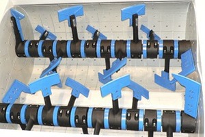
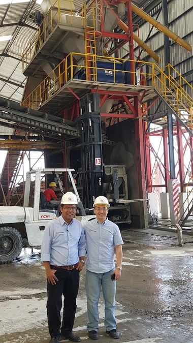
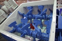
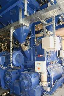
The paper focuses on the mixer shown in Fig.1: it is a twin shaft mixer by Sicoma-OMG Group, and it presents many advantages, such as quality of concrete and efficiency of the mixing procedure.
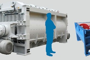
The sizes of Sicoma twin shaft mixers range from 0.5 to 9 m3 of vibrated concrete (in Fig.2 an idea of the available range of sizes).
There are two horizontal shafts with one or two motors and a gearbox, depending on the dimensions. The gearboxes are epicyclical type. The first reduction is performed by a pulley transmission equipped with a constant-velocity universal joint, to keep the shafts synchronised.
The tank has a typical omega shape and it is coated with Ni-Hard Cast Iron with 530 HB minimum Brinell hardness. The mixing arms have a thin profile to avoid the accumulation of material and they are made of spheroidal cast iron.
The mixing blades are made of Ni-Hard cast iron. Their large number, their position and their orientation guarantee the right combination between the effects of rotation and circulation of the material during the mixing action.
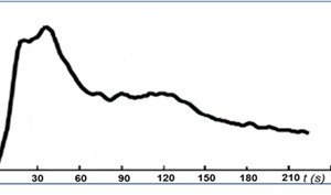
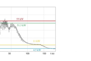
During a mixing cycle, in the power consumption curve, one can identify a first mixing phase called “dry phase”, where sand and cement are input without water, and a subsequent “wet phase” after the introduction of water. Afterwards, the regime phase is characterized by a quasi-stationary power absorption and regards the final mixing cycle before discharge (Fig.3).
The study of the mixing phenomenon during the different described phases can be carried out in terms of power consumption.
3 Experimental campaigns
In this research work, experimental tests were performed, and the correlation between the tank filling level and the power absorption was investigated in terms of peak value and regime value. The mixer used for the tests was a model 4500/3000 by Sicoma-OMG, located in Ellera-Perugia (Italy) at the Gradassi’s concrete production plant. In Table 1 the main mixer’s geometrical parameters are reported. The mixer usually processes 4.5 m3 of mixture and returns 3 m3 of vibrated concrete with a filling level h equal to 0.253 m.
The analysed mixer has two motors with a nominal installed power of 55 kW. In these experimental campaigns, the same mixer was filled with different filling levels h, processing different mixing volumes, with the aim of studying the influence of filling levels on the power consumption for the same concrete mix composition. The processed concrete was a standard concrete mixture with a cohesion equal to 1300 N/m2 in the dry phase, a regime shear yield stress of 600 Pa and with a degree of humidity of about 5%.
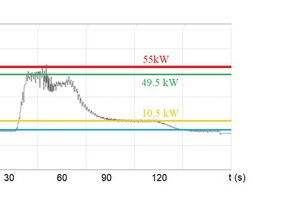
During the tests, measurements of power consumption were carried out. Fig. 4 shows one of the resulting experimental power consumption curves, where the filling level h was equal to 0.253 m. In the figure, the installed nominal power (55 kW), the total peak power (49.5 kW), the total regime power (10.5 kW), the no-load power (4.5 kW) for a single shaft and a single motor are highlighted.
Then, in Fig.5, the experimental power consumption is shown with the filling level h equal to 0.344 m and a consequent processed volume equal to 5 m3.
Other experimental tests were carried out with the same mixer and mixture composition, but with different filling levels h, so that the processed mixing volume changed. The main results are reported in Table 2.
4 Conclusion
In this paper, experimental tests are performed in a concrete twin shaft mixer to evaluate the power consumption as a function of the filling level of the mixer. The transient and regime phases of the mixing cycle were studied and characterized in terms of values of peak power and regime power. Variations of the filling level and the consequent processed volume were analyzed: results show that increasing the filling level for a given mixer, the total regime power remains quite constant, while the total peak power presents a slight increase.
The results of this research can be useful to design and produce machines which allow energy saving and enhanced production rates. In-fact, the aim of this paper was to study the machines to obtain a greater production volume of concrete with the same installed power.

