Residual concrete recycling in Southern Russia
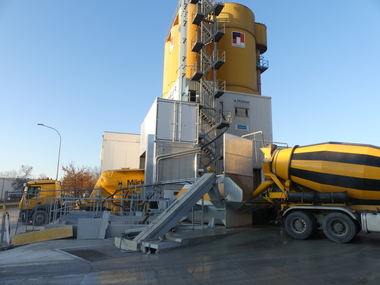
When the newly constructed precast plant in the Russian city of Shakhty was officially commissioned at the end of September 2012, this was also a milestone in the successful history of Bibko Umwelttechnik und Beratung GmbH, a company providing environmental engineering and associated consultancy services. The plant includes not only the precast production line and work stations, which define a new standard in terms of their processes and equipment, but also a comprehensive recycling concept.
The Shakhty facility mainly produces facade and wall units, as well as stair systems. The plant manufactures either exposed-aggregate or standard concrete surfaces depending on customer specifications or project requirements. For this reason, the Bibko recycling system is divided into two areas:
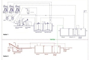
Building 1 accommodates the concrete mixing unit comprising three mixers. After the mixing process, the concrete is fed onto one of the two bucket conveyor systems and transported to the required location in the factory. In Building 2, the precast elements are finished using high-pressure water lances to create exposed-aggregate surfaces.
Reduced handling cost
A separate concept was developed for each area because the requirements for the recycling process or recycling system differed from those in the respective other area. However, an interface connects the two systems to each other.
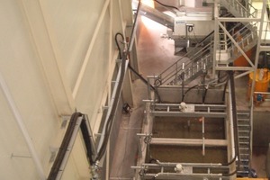
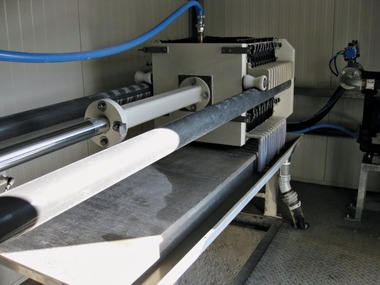
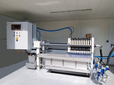
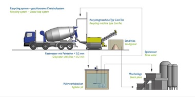
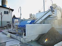
The largest residual concrete quantities are generated in the mixing area, which is why a ComTec 20 Bibko recycling system was installed in this location. Residual concrete quantities can be conveyed directly to the system from the three mixers or from the bucket conveyors. Washing water used for the mixers and bucket conveyors is also directly fed into the recycling system. The handling costs of residual concrete are thus reduced considerably.
The recycling system then performs the actual recycling or washing process in which the material is separated into a mineral aggregate with particles larger than 0.2mm (sand, gravel) and water with cement-containing fines smaller than 0.2mm. The aggregate is discharged from the system via a spiral conveyor mounted on the ComTec recycling unit whereas the fines and the residual water flow into a pump sump via the water overflow of the machine. At this point, a pump conveys the water with the fines into the first agitator pit. The agitator located in this pit keeps the fines in suspension and prevents their sedimentation. Residual water from this pit is used for rinsing the hopper that takes up the washing water and residual material resulting from the washing process of bucket conveyor and mixers but also for water supply to the Bibko material conveying system.
Satisfied demand
The system includes a second agitator pit to make residual water with uniform specific properties available for the actual mixing process. Whereas the first pit serves as an interim buffer to accommodate the fluctuating amount of residual water, residual water is pumped into the second pit after a certain period of time (mostly in the morning of the following day). This process compensates fluctuations in the density of the residual water and in the chemical reaction rate (hydration) of the cement particles in the course of the production day.
The volume of the agitator pit has been dimensioned to provide the amount of water needed for a single production day. Submersible pumps located in the agitator pit pump the residual water to the mixing unit or to the water weighing system.
Integrated density measurement
Another element to control the quality of the produced concrete is the density measurement system installed in the second agitator pit. Measured densities are continuously transmitted to the control system of the concrete mixing unit to make any required corrections or adjustments.
The floor of Building 1 includes another pump sump in order to be able to also clean the concrete spreaders. This sump is part of the Bibko material conveying system and takes up all the material that results from the cleaning of the concrete spreaders. Using water as a conveying fluid, the residual material is fed into the ComTec recycling system for processing.
If the above recycling process generates an excess amount of water in Building 1, the plant layout provides the option of pumping this excess water into a multi-chamber settling tank.This system relies on the sedimentation of fines so that the last chamber of the tank contains clarified water. This water is used to refill the first agitator pit and as washing water for the recycling system. It can also be fed directly into the concrete mixing unit if and when required.
Actual recycling process
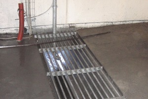
When finishing the exposed-aggregate concrete elements using high-pressure water lances, the part of the concrete surface that has not yet hardened due to the application of chemical retarders is washed off. In this process, the top layer consisting of cement-containing particles, sand and small mineral particles is detached. This material is collected in a chute together with the used water. From this chute, the material is conveyed into the Bibko RWS recycling system where the actual recycling process takes place.
Particles in excess of 0.2mm are discharged via the screw included in the system whereas the excess water containing the fines smaller than 0.2mm is fed into the pump sump via the machine overflow. At this point, a pump conveys the water with the fines into a multi-chamber settling tank. The last chamber of the tank includes the rinsing pump for the chute that takes up the washed-off material but also the transfer pump conveying the material to the system located in Building 1.
Closed-loop system
Besides the above process used to produce exposed-aggregate concrete elements, Building 2 also accommodates processes that rely on the application of acids. The acid/water mix generated in this step is also collected and fed into the first chamber of the settling tank. This mix reduces the alkaline pH value of the residual water.
The transfer pump or transfer line acts as the interface between the two systems. In the event of any shortage of water required for concrete production in Building 1, the required water is conveyed from the settling tank located in Building 2. As a result, the system always supplies a sufficient amount of mixing water for concrete production.

