Cast-in Peikko HPM-L anchor bolts exposed to fatigue loading (Part 1)
The first part of this article discusses fasteners exposed to fatigue loading and explains how to determine their characteristic fatigue resistance. Part 2 will present the outcomes of related tests and analyses and is scheduled for publication in the next BFT issue.
1 Introduction
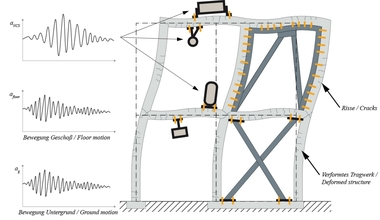
Anchors and embedded parts such as anchor channels and headed anchor bolts are frequently used in the construction industry to transfer loads into concrete components. In conventional reinforced concrete construction, such fasteners are primarily exposed to static or quasi-static loading. However, applications in which cyclic loads must be considered are becoming increasingly important owing to more and more slender structures and the use of state-of-the-art equipment and machinery. EN 1992-4 [1] defines typical fields of use, which include fasteners for elevators, cranes, crane runways, and machines with moving parts. However, frequently repeated impacts resulting from high-speed rail traffic or temperature fluctuations in façade elements should also be considered. In such cases, fatigue verification must be conducted to prevent failure of the anchorage and the connected components due to material fatigue.
2 Fasteners exposed to fatigue loading
2.1 Fatigue strength of fasteners
The fatigue behavior of fasteners depends on the material characteristics of the anchoring system components involved in load transfer, including the type of fastener, the surrounding concrete, and their interaction. Depending on the type of fastener, tensile loads are transferred into the anchor base using the principles of mechanical interlock, friction or bond, or a combination thereof. Consequently, the structural behavior of fasteners is characterized by different failure mechanisms. In the case of fatigue loading, the types of failure that can generally occur resemble those under static loading, which applies to both tensile and shear loads. Besides steel failure of the fastener, they also include certain types of concrete failure such as break-out, pull-out, splitting, or edge failure.
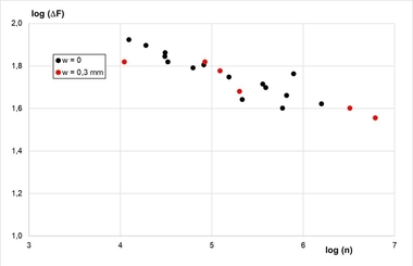
Unlike static structural capacity, fatigue resistance is a time-dependent variable, and the relevant failure mode may change depending on the number of load cycles. Previous studies ([12], [13]) show that the S-N curves for steel and concrete failure have different slopes, as illustrated in Fig. 2.1. Thus, steel failure is usually the leading type of failure for a greater number of load cycles, under the condition that fasteners are mounted at a sufficiently large distance from the edge and other anchors. This is also confirmed by further studies of fasteners positioned far from the edge, where fatigue failure due to steel fracture was frequently observed [19].
According to [14], the relatively flat S-N curve for concrete failure is attributable to the fact that initial cracking occurs in the concrete anchorage zone from about 30% of the maximum load, which exhibits stable crack propagation during the service life and up to about 70% of the maximum load. The shape of the failure cone has a favorable effect because a larger area needs to be cut through with increasing crack depth. The stress at the crack tip thus decreases due to the interlocking effect along the resulting crack. Fatigue resistance in the event of steel failure depends on many different factors such as the shape, size, material, manufacturing process, and surface finish of the fastener. Failure typically originates from points of high stress concentration, where cracks develop that propagate with increasing load cycles. Such notches can be caused by a change in geometry, a heterogeneous material structure, or local load application. In fasteners, they are typically caused by production-related weld seams, threads, or cross-sectional offsets [19].
2.2 Design rules
EN 1992-4 [1] specifies the design rules for fasteners in concrete components. This standard requires verification of fatigue resistance for fasteners frequently exposed to repetitive load cycles. Typical applications include cranes, machines with moving parts, and elevator guide rails. In engineering practice, it is recommended that a fatigue analysis be conducted if actions with more than 1,000 load cycles occur under pulsating tensile load and more than 100 load cycles under shear or inclined loading in the expansion zone [18]. Verification under fatigue loading uses the partial safety concept as specified in the design rules contained in the Eurocodes [15]. Accordingly, it must be verified that the design actions are smaller than or equal to the design resistance. Due to the different failure mechanisms, this verification is conducted separately for each load direction and potential type of failure. The fatigue resistance of fasteners depends on the specific product owing to different components, geometries, materials, and manufacturing processes. Suitability of the products to be used under fatigue loading must thus be verified using appropriate test and assessment methods. The relevant European Technical Product Specification defines the resulting resistance values and conditions for use. EN 1992-4 [1] specifies the fatigue resistance for all types of concrete failure as 50% of the static value for 2 × 10⁶ load cycles. An essential criterion for cyclic loading is a clearance-free force transmission within the fastening system. There must be no gap between the fastener and the attachment part to avoid sudden impact, such as with alternating shear loads with changing signs. The fatigue design rules specified in EN 1992-4 [1] apply to post-installed fasteners and headed anchor bolts. This standard does not cover fatigue verification of anchor channels, which is why separate design rules are available for this type of product. The following section provides an overview of the currently applicable design rules for the various types of fasteners referred to above.
2.2.1 Post-installed fasteners
The fatigue design of post-installed fasteners such as mechanical and chemical anchors is conducted in accordance with EN 1992-4 [1] or Technical Report EOTA TR 061 [7]. The related rules refer to actions resulting from pulsating tensile and shear loads, alternating shear loads, and combinations of tensile and shear loads. Cyclic shear loads involving a lever arm, such as for installation at a certain distance, are not covered since the shear loads occurring in this type of use cause additional bending stress in the anchor, which may reduce its fatigue resistance. Products must have a European Technical Assessment (ETA) issued based on European Assessment Document EAD 330250 [6]. Tables 2.1 and 2.2 summarize the fatigue verifications required for mechanical anchors in tension and shear. For groups of fasteners, the resistance to steel failure and pull-out must be verified for the anchor exposed to the highest load. The other types of failure must be verified for the entire group of anchors. In the verification conducted for the anchor exposed to the highest load, the resistance is lowered by a reduction factor ΨFN for tensile loading and ΨFV for shear loading to account for uneven load distribution within the group. For combined tensile and shear loads, the corresponding interaction verifications must be performed separately for each type of failure.
Fatigue verification of cast-in headed anchor bolts is conducted in accordance with EN 1992-4 [1], as described in section 2.3.1. As mentioned above, these rules exclusively apply to fasteners with verified suitability for fatigue loading. However, European Assessment Document EAD 330250 [16] governing the verification of headed anchor bolts does not contain any provisions for fatigue qualification of the products. This is why the use of headed anchor bolts as fasteners exposed to fatigue actions is currently not covered in design and construction practice.
3 Description of HPM L anchor bolts
3.1 Applications under static and quasi-static loading
Peikko HPM-L anchor bolts are made of ribbed B500 B reinforcing steel in diameters of 16, 20, 25, 32 and 40 mm, including two hexagon nuts and two washers. One end of the bolt features an anchor head, while the other end is fitted with an M16, M20, M24, M30, or M39 thread. The anchor bolt is set in concrete up to its anchoring depth mark. The following figure shows the anchor in installed position. Fig. 3.1 indicates the most important dimensions for design and installation. The anchor head size is dimensioned such that pull-out failure does not occur. In addition, the anchorage depth is sufficiently large to prevent concrete failure due to conical concrete break-out under static and quasi-static loading. Steel failure should thus be expected under fatigue loading.
3.2 Filling the annular gap
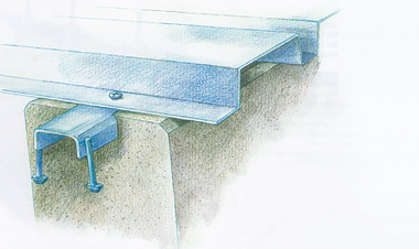
The attachment parts in conjunction with anchor bolts have standard hole clearances. It is known from previous investigations that the hole clearance between the attachment part and the anchor thread must be filled to prevent premature fatigue failure, particularly under pulsating or alternating shear loads. Filling can be achieved by mechanical filling using a clamping sleeve (Fig. 3.3) or with a suitable grouting mortar (Fig. 3.4). The dimensions of the clamping sleeve (i.e. diameter, wall thickness, length) must match those of the attachment part, and the clamping sleeve is driven into the annular gap.
During grouting, the mortar is squeezed into the annular gap through a washer with a lateral hole. In both cases, the annular gap is filled completely. However, the installation effort for driving in the sleeves is comparatively high for medium to large thread diameters. Furthermore, the space available above the attachment part is limited in many cases.
4 Qualification of anchor bolts for fatigue loading
4.1 Presentation of the qualification guideline
4.1.1 General information
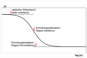
There are three assessment methods for determining the characteristic fatigue resistance of fasteners: Test method A should be used if a continuous fatigue resistance function is to be provided depending on the number of load cycles (see Fig. 2.1a). This test method is equivalent to the interactive method according to [12], [13] and is described in section 4.1.2.
Test method B may be used if only the value of the characteristic fatigue limit resistance for an infinite number of load cycles is to be specified. This test method is a simple procedure and is described in section 4.1.3.
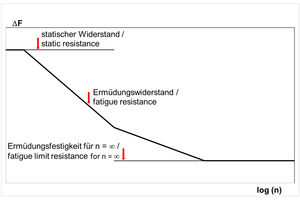
Post-installed bonded anchors, mechanical steel anchors, and cast-in anchor bolts made of carbon steel and stainless steel can be assessed using test method C. This method provides a linearized function of fatigue resistance depending on the number of load cycles (see Fig. 4.1b) and simplifies the real-life behavior shown in Fig. 4.1a. Furthermore, this test method makes it possible to reduce the required number of tests significantly. This reduced number of tests is compensated for by a more conservative assessment of the tests. The effective embedment depth amounts to hef ≥ 60 mm or hef ≥ 4 d. The test methods must not be mixed with each other.
4.1.2 Method A
Method A attempts to accurately reproduce the real (S-shaped) curve of the fatigue function. For this purpose, a simplified 5% fractile value curve is derived from the mean fatigue function determined from the test results at different stress levels.
4.1.3 Method B
In method B, the repeated loads consist of a constant lower stress level and an upper stress level with the same sign (i.e. no alternating load). They should be applied to the specimen to fatigue failure or until a limit number of cycles is reached. Specimens that reach the limit number of cycles without failure (run-through) must be tested again at a higher stress level (proof of non-damage to the specimen). This run-through test is conducted to determine potential damage to the specimen despite reaching the limit number of cycles. This method only provides the characteristic fatigue limit strength for an infinite number of load cycles (n → ∞).
4.1.4 Method C
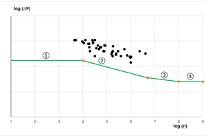
This method aims to simplify the comparatively complex method A in such a way that a polygon with four linear sections of different gradients is obtained by linearizing the S-shaped fatigue function in a section-by-section approach.
Tests must be planned such that fatigue failure occurs between n = 104 and n = 1 × 10⁶ load cycles for carbon steel and between n = 104 and n = 1 × 10⁷ load cycles for stainless steel.
The fatigue tests must be distributed such that six to eight tests fail between 104 and 105 load cycles, approximately six to eight tests fail between 105 and 1 × 10⁶ in tension, or between 105 and 5 × 10⁶ in shear. For stainless steel, two tests between n = 2 × 10⁶ and n = 1 × 10⁷ must fail. The tests can be assessed together if the fatigue tests are statistically equivalent in terms of failure for different test parameters (cracked and uncracked concrete, different materials, etc.). At least 20 tests are required, and at least 15 tests must have been conducted for the most unfavorable variant or configuration.
Statistical equivalence is determined using the quantile lines and a 90% confidence level. Statistical equivalence is sufficient if the results of different diameters or the results in cracked and uncracked concrete lie within the range between the 5% quantile line and the 95% quantile line (prediction range) of the unfavorable or leading tested dimension (largest number of test results) in uncracked concrete. The lowest 5% quantile level is determined for the unfavorable condition in terms of dimension or cracked and uncracked concrete. This accounts for the scatter of the test results, and the comparison of the different dimensions or concrete conditions (cracked/uncracked) can be performed using stresses instead of forces.
The section-by-section linear fatigue function comprises the sections listed below. The linear regression of the test data is performed on a double-logarithmic scale using the least-square method.
Section 1: The upper horizontal level is the characteristic fatigue resistance for n < 104.
Section 2: linearly decreasing curve between 104 ≤ n ≤ 5 - 106 with the gradient m1
Section 3: linearly decreasing curve between 5 - 106 < n ≤ 108 with the gradient m2. Here, m2 ≤ m1 or m2 = 2 m1 - 1 applies.
Section 4: The lower horizontal level is the characteristic limit resistance for n > 108 (n = ∞).
REFERENCES/LITERATURE

![Fig. 2.1: Relevant failure modes for fasteners exposed to fatigue loading according to [12], [13]](https://www.bft-international.com/imgs/2/1/7/7/3/5/3/tok_c4328fab2908c4a45f770f1af4890c5d/w300_h200_x600_y388_HA_1272_Fig._2.1_Sippel-Peikko-51efeeaa7486e8fd.jpeg)
![Table 2.1 Required verifications for anchors in tension according to EN 1992-4 [1]](https://www.bft-international.com/imgs/2/1/7/7/3/5/3/tok_e05f4a6f68dab493a29dd225f0af70d1/w300_h200_x380_y220_Table_2.1_online-f294e848a64650bf.jpeg)
![Table 2.2 Required verifications for anchors in shear according to EN 1992-4 [1]](https://www.bft-international.com/imgs/2/1/7/7/3/5/3/tok_d1913875865554eb34eba110c9942760/w300_h200_x377_y171_Table_2.2-431d2cfa922587cb.jpeg)
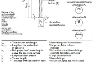
![Fig. 3.1: Dimensions of HPM L anchor bolts ([3], [4], [5])](https://www.bft-international.com/imgs/2/1/7/7/3/5/3/tok_b4718a1fdb1a08db2ac15b7edbce5f38/w300_h200_x456_y156_Fig_3.1_online-a14bce5bdcf2e8fb.jpeg)
![Fig. 3.2: General installation of the HPM-L anchor bolt in concrete defining the length, embedment depth, and fastening depth ([3], [4], [5]) ](https://www.bft-international.com/imgs/2/1/7/7/3/5/3/tok_9757d872a06fd6462b3c5c2ad9ef8cc5/w300_h200_x244_y110_Fig._3.2_online-86aab491a5aab204.jpeg)
![Fig. 3.3: Clampingsleeve ([5])](https://www.bft-international.com/imgs/2/1/7/7/3/5/3/tok_d1762eb223262450b39614d39d14bc79/w300_h200_x419_y148_Fig_3.3_online-a221576bed0956cc.jpeg)
![Fig. 3.4 Specially designed washer with lateral hole and grouting mortar ([5])](https://www.bft-international.com/imgs/2/1/7/7/3/5/3/tok_47a976bce5917d378352e9e483ea4947/w300_h200_x421_y162_Fig_3.4_online-ff0be1d6c19a5c8c.jpeg)
