Cast-in Peikko HPM-L anchor bolts exposed to seismic actions (Part 2)
The first part of this article discussed the various test guidelines for fasteners and outlined new developments in test guidelines and the associated assessment documents for anchors and headed anchor bolts (see BFT 08/2024 for the first part). Part 2 of this article discusses the outcomes of the tests.
2.4 Assessment of the tests
2.4.1 α reduction factor
The α reduction factors applied in the C2.1 and C2.2 static reference test series are determined exclusively based on the mean maximum load-bearing capacity. The EAD defines a specific maximum bearing capacity limit value based on the mean bearing capacity for concrete breakout in tension. In shear, the mean shear capacity (steel failure) from tests with a normal crack width
(Δw = 0.3 mm) is used. Alternatively, the mean calculated bearing capacity of steel may be used.
In the C2.3, C2.4 and C2.5 cyclical test series, three criteria are assessed for each of the series. For each of these criteria, a specific α reduction factor is determined. The final α reduction factors represent the minimum derived from the respective individual values. The three criteria are
successful completion of the cyclical load history
adherence to a displacement criterion (≤ 7 mm) under service load after completion of the load cycle
fulfillment of the requirements for the mean failure load in the residual bearing capacity tests.
2.4.2 β-reduction factor
In category C2, a second reduction factor β is introduced to determine characteristic seismic resistance. This β reduction factor accounts for the scatter of the ultimate loads in the residual bearing capacity tests with cyclic loading compared to the scatter of the ultimate loads in the static reference tests. Scatter is defined relative to the coefficient of variation V. Based on the reduction factors for the individual test series, the relevant β reduction factor for tensile and shear load is calculated in the final step.
2.5 Transfer of test methods to cast-in anchor bolts
Cast-in anchor bolts are designed in the same way as headed or post-installed anchors in accordance with EN 1992-4 [2]. Anchor bolts are qualified in accordance with the EAD [6], whose test specifications essentially correspond to those for anchors [16] and were adjusted to the specifics of cast-in anchor bolts only to a minor extent. This applies, for example, to the rules for considering suspension reinforcement and rules for executing welds for multi-part anchor bolts. The rules contained in the EAD [16] or in TR 049 [7] for seismic applications for undercut anchors can also be applied. However, adjustments must be made regarding the production of the test slabs or crack bodies. While it is possible to adjust anchor installation to the actual crack path, care must be taken to ensure that cast-in anchor bolts lie in the subsequently occurring hairline crack across their entire length. Meanwhile, highly sophisticated concrete pouring methods are available for this purpose that use aluminum foil for crack formation. The essential steps of this process were added to the EAD [6].
Peikko Group put its HPM 16-L anchor bolt to the tests referred to above in accordance with the EAD [6]. We discuss the test results in the following sections.
3 Tests of HPM16-L Peikko anchor bolts under simulated seismic actions
3.1 Reference tests under tensile and shear loads
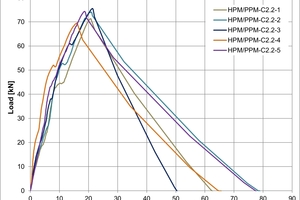
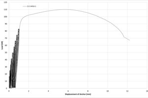
The reference tests for wide cracks (Δw = 0.8 mm) were conducted under tensile and shear loading. Fig. 3.1 shows the load-displacement curves in tension and shear. All requirements for maximum loads, displacement values, and the associated scatter were met. Since the C2.1a test series conducted for low-strength concrete had already identified steel failure as the predominant phenomenon, additional tests of high-strength concrete were not necessary.
3.2 Tests under pulsating tensile load
Tests were conducted under gradually constant pulsating tensile load with subsequent determination of the residual bearing capacity in 0.8 mm wide cracks. Fig. 3.2 a) shows an example of the load-time and displacement-time diagram of a test, while Fig. 3.2 b) shows the load-displacement curve of the test. All requirements for load changes, maximum loads, displacement values, and the associated scatter were met.
3.3 Tests under alternating shear load
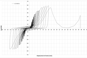
These tests were initially conducted applying the shear load Vmax = 0.85 ∙ Vu,m,C2.2 = 0.85 ∙ 72.95 = 62 kN specified in the EAD [6] (cf. Table 2.3). The first test failed prematurely after 60 load cycles. Fig. 3.3 b) shows the load cycle displacement curve. The load was then reduced to Vmax,red = 45 kN. Under this maximum load, the required load cycles could be applied in all tests. Fig. 3.4 shows an example of a load-cycle displacement curve as well as the load-time and displacement-time diagrams.
The reduced shear load results in a reduction factor αC2.4a = 45/62 = 0.73. All other requirements were met in the test series at Vmax = 45 kN. It should be noted that the reduction determined in these tests for the Peikko anchor bolts compared to previously approved anchoring systems (anchors and anchor channels) tends to be in the upper portion of the identified scatter range. This is primarily due to the benign, more ductile behavior of the B500B base material used compared to quenched and tempered free-cutting steels used for anchors.
3.4 Tests under constant tensile load and varying crack widths
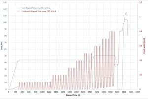
These tests were conducted applying the constant tensile loads Nw1 and Nw2 specified in the EAD. However, only one test cylinder with Nmax = 50 kN was available at the time of performing the tests. This is why the tests were conducted at Nw2 = 50 kN, i.e. a load that was slightly too low, instead of the required Nw2 = 51.56 kN determined in the calculation. This results in a reduction factor that was considered when assessing the tests (see section 3.5). Figs. 3.5 a) and b) show the displacement values and crack widths as a function of time for a single test. Both diagrams also include the gradually constant permanent load over time.
The diagrams clearly show that a constant permanent load Nw2 increased by 3 % will not lead to a significantly different result regarding displacement or residual bearing capacity.
3.5 Determination of performance
Table 3.1 shows the resulting reduction factors for seismic category C2.
The subsequently determined characteristic resistance values apply to fasteners with the tested anchorage depth as well as to any smaller anchorage depth. The characteristic resistance values for seismic actions given below are limited by the values for static and quasi-static loading. The calculated characteristic resistance values can be considered to be conservative for all HPM-L dimensions. Table 3.2 provides a summary of the resistance values for all HPM-L anchor bolts.
In the case of shear loading, only steel failure is considered in the assessment.
Similar to the characteristic tensile resistance values, the shear load resistance calculated for HPM 16-L anchor bolts can be applied to all HPM-L sizes.
In addition to the bearing capacity requirements (absorbable loads), many use cases also include requirements for the deformation of fastener connections. On the one hand, this refers to the functionality of components and attachments as well as the support conditions assumed in a calculation (such as rigid support) to determine the actions. Table 3.4 lists the displacement values determined for tensile and shear loads.
3.6 Further assessment aspects
If the presence of an annular gap between the fastener and the attached part, the forces acting on the fasteners are amplified by the hammer effect on the fastener in the event of shear loading. The design approach specified in EN 1992-4 [2] considers this effect by introducing a reduction factor for the bearing capacity of the fastener.
Tests for seismic category C2 were conducted exclusively for anchor bolt size HPM16-L. This was because the applied loads were already high and steel failure was identified as the predominant phenomenon. For larger sizes, the anchorage depth would increase, making steel failure even more likely. To avoid tests of larger sizes, the load level of HPM-L size 16 is transferable to all larger sizes.
The characteristic resistance values determined for category C2 can also be used as characteristic resistance values for seismic category C1. The performance assessment according to category C2 generally results in a lower performance compared to the performance assessment specified in EAD 330232-01-0601 [16] for category C1. This is why the characteristic resistance values determined for category C2 also apply to category C1.
The test results clearly demonstrate that the previous test conditions for the qualification of post-installed fasteners exposed to seismic actions can be transferred to Peikko cast-in anchor bolts without any restrictions. Only minor adjustments are required in the production of the test specimens (see section 2.5). For these reasons, it makes sense to also transfer the European Technical Product Specification for seismic actions to other sizes.
4 Summary and outlook
Considering seismic actions on fasteners requires specific qualifications for the fastener. During the last few decades, related guidelines were elaborated and increasingly adapted to the real behavior of structures exposed to seismic actions. More recently, a guideline was drafted for the qualification of cast-in anchor bolts. The corresponding tests of HPM16-L Peikko anchor bolts were conducted simultaneously with the preparation of the guideline. As expected, the tests yielded favorable results, which are mainly due to the low sensitivity of the anchor bolts to large crack widths (owing to their large head diameters). The observed reduction under alternating shear load lies in the upper portion of the previously determined range. In the meantime, the European Technical Assessment ETA 02/0006 [3] was republished after adding the characteristic values for seismic and fatigue loading [18].
REFERENCES/LITERATUR

![Fig. 3.1: Load-displacement curves of the reference tests, according to [15] a) Series C2.1a: Tensile load](https://www.bft-international.com/imgs/2/1/3/3/1/4/9/tok_6bd7bdb725dcd35ff232e21618a8b00a/w300_h200_x600_y431_HA_1252b_Abb.3.1a_Bild1-79edc18b28dec8f0.jpeg)
![Fig. 3.2: Illustration of the results of test 1 of series C2.3, according to [15]; a) Series C2.3: Pulsating tensile load and associated displacement, test 1](https://www.bft-international.com/imgs/2/1/3/3/1/4/9/tok_42fb1dfd6bee2e2e5f771b74ef433042/w300_h200_x600_y387_HA_1252b_Abb.3.2a_Bild3-387ce5d1ff11de33.jpeg)
![Fig. 3.3: Illustration of the results of test 1 of series C2.4, according to [15]; a) Series C2.4: Load cycles and associated displacement, Vmax = 62 kN, failure after 60 load cycles](https://www.bft-international.com/imgs/2/1/3/3/1/4/9/tok_b2fc4a627b0602d0e7a6d3cb8248c06c/w300_h200_x600_y387_HA_1252b_Abb.3.3a_Bild5-98f546ea5fd4fb7b.jpeg)
![Fig. 3.4: Illustration of the results of test 1 of series C2.4 with reduced shear load, according to [15]; a) Series C2.4: Load cycles and associated displacement, Vmax,red = 45 kN, failure after 60 load cycles](https://www.bft-international.com/imgs/2/1/3/3/1/4/9/tok_65fdc6a7f47eb89acfa9597b8e91f6b8/w300_h200_x600_y387_HA_1252b_Abb.3.4a_Bild7-ead1d821407ecdf2.jpeg)
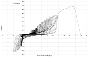
![Fig. 3.5: Illustration of the results of test 1 of series C2.5, according to [15]; a) Series C2.5: Displacement values and constant permanent load over time](https://www.bft-international.com/imgs/2/1/3/3/1/4/9/tok_f1ea7bccf2344d1f1ba6041fa48cff25/w300_h200_x600_y387_HA_1252b_Abb.3.5a_Bild9-34f9cf87d793a2a2.jpeg)
