Cast-in Peikko HPM-L anchor bolts exposed to seismic actions (Part 1)
![Fig. 2.1a: Examples of seismic actions: Structural response to ground motion and schematic acceleration curves (according to [13])](https://www.bft-international.com/imgs/2/1/2/1/7/8/4/HA_1252a_Fig.2.1a_Abb2.1a-f119c310efdcefbd.jpeg)
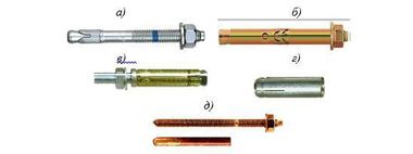
![Fig. 2.1b: Examples of seismic actions: Cyclic actions on the fastener with changing crack widths and cyclic tensile and shear loads (according to [12])](https://www.bft-international.com/imgs/2/1/2/1/7/8/4/HA_1252a_Fig.2.1b_Abb2.1b-538748619a60249e.jpeg)
The first part of this article explains the various test guidelines for fasteners and discusses new developments in test guidelines and the associated assessment documents for anchors and headed anchor bolts. Part 2 will present the outcomes of the tests and is scheduled for publication in the next BFT issue.
1 Introduction
A design method for using anchors and headed anchor bolts for load-bearing connections or fastenings in seismic areas was previously only available in technical specification documents, but not in a European standard. A set of rules has long been available for nuclear facilities [21]. However, due to the associated stricter requirements, it is transferable to standard buildings or engineering structures only to a limited extent. Even though Section 7 of EN 1998-1 [8] contains specific rules for composite structures made of steel and concrete, the related provisions do not cover connections using anchors and headed anchor bolts.
The current rules contained in EN 1992-4 [2] distinguish between connections of load-bearing components and connections of load-bearing and non-load-bearing components. They specify different performance categories for certain seismic actions. The corresponding product-specific parameters are described in the respective European Technical Product Specifications.Rules for qualifying fasteners exposed to seismic action are currently only available for post-installed fasteners (anchors) (see [16], [7]). Different seismic performance categories are assigned to the individual test conditions specified therein.
In the following section, we briefly discuss the various test guidelines for fasteners and present significant new developments in test guidelines and the associated assessment documents for anchors and headed anchor bolts. We explain the newly adopted rules and compare them with recent test results obtained for Peikko HPM 16L anchor bolts.
2 Discussion of existing guidelines
2.1 General
Until recently, no specific requirements applied to fasteners such as metal or bonded anchors and headed bolts used in concrete for general building structures in European seismic regions. Only for special applications, such as in plant engineering or nuclear facilities, were requirements for seismic design situations specified.
According to the common international understanding, areas can be designated as regions with low seismicity if no earthquakes equal to or greater than magnitude 6 have occurred there. This means that EN 1998 [8] permits the application of reduced or simplified seismic design methods depending on national requirements and specifications.
Since no earthquake-specific requirements are stipulated for structures exposed to very low seismicity, EN 1992-4 [2] also exempts fasteners from such requirements. Performance category C1 reflects the aspect of reduced or simplified methods for structures for fasteners, including a less demanding qualification of products compared to C2 that considers comparatively smaller loads acting on the anchorage base (i.e. crack opening in the event of an earthquake).
In earthquake design, actions from tension, shear, and diagonal tension can be relevant. A distinction must be made between
connections of load-bearing components, such as steel columns or frames on a concrete foundation, and
connections of non-load-bearing and load-bearing components.
During seismic action, both the fasteners themselves and the anchorage base (concrete) can be subjected to cyclic loading (Fig. 2.1, according to [13] and [12]). More specifically, the potential cyclic crack width variation to be expected in the reinforced concrete component acting as the anchorage base also has an influence on the connection’s bearing capacity. More stringent requirements have recently been specified for fasteners in Europe to account for these influences.
In Europe, post-installed fasteners are tested for their performance under seismic action in accordance with EOTA TR 049 [7]. This guideline distinguishes between two performance categories, namely C1 and C2, for which specific tests and test methods apply.
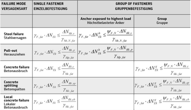
The existing seismic performance tests for fasteners generally consist of one or more of the following components:
1. Tests to check the load-bearing capacity of a fastener under tensile and shear load in cracked concrete
2. Simulated seismic load tests applying pulsating tensile load or alternating shear load
3. Tests with constant tensile load on the fastener in opening and closing cracks (crack movement test)
Three load patterns are currently used for simulated seismic load cycle tests. For tensile loading, these include:
constant pulsating tensile load,
gradually decreasing pulsating tensile load and
gradually increasing pulsating tensile load.
The alternating shear load pattern is similar, but the load changes symmetrically around zero.
In crack movement tests, a fastener is installed in a closed hairline crack and loaded by a constant tensile load (Nw), which is a fraction of the maximum bearing capacity.
More recent studies ([12], [13]) found that the above-mentioned method significantly underestimates the residual displacement of the fastener during crack opening and significantly overestimates the residual bearing capacity after crack opening. In addition, the investigations showed that in real buildings, the cracks in the component do not only open because of changing horizontal ground acceleration; they are also closed completely by external compressive forces. That is why this behavior is simulated in the latest test guidelines.
2.2 DIBt guideline for anchor fastenings in nuclear power plants
In nuclear power plants or other nuclear facilities, both cast-in and post-installed anchors are used very frequently. A fundamental aspect for using anchors in nuclear power plants is their correct functioning under special conditions that may occur during the service life of the plant. These conditions include impact loads, seismic actions, and cracking due to seismic loads with a width wk≥ 0.5 mm, but the usual technical approvals or assessments do not cover them. To close this gap, additional experimental tests are required to prove the suitability and proper functioning of the anchors and to determine the permissible conditions for use under the above-mentioned impacts.
Three different use categories (A1, A2, and A3) must be considered for anchors used in nuclear power plants. These three categories are based on different load frequencies to be expected during the service life of the plant (see Table 2.1).
Category A3 assumes that the action will only occur once during the service life of the structure. This includes events such as the maximum expected earthquake (design earthquake), flooding, an airplane crash, or an explosion. Safe shutdown of the nuclear plant must be ensured under these conditions. Since cooling water is required for the shutdown, among other things, the fasteners of the corresponding cooling lines must function properly.
2.3 Qualification of fasteners according to European guidelines
In Europe, post-installed anchors are assessed for their performance under seismic actions in accordance with EOTA TR 049 [7]. This guideline distinguishes between two performance categories, namely C1 and C2, for which specific tests and test methods apply. Performance category C1 was first included in ACI 355.2 [14]; it was adopted unchanged in the European guidelines. Both categories are defined in European standard EN 1992-4 [2] and refer to the degree of seismicity relative to ground acceleration and building performance class, which are described in EN 1998-1 [8].
In addition, the German national annex DIN EN 1992-4/NA [9] relates the performance classes to the expected damage to the base material, which is characterized by the calculated crack width. This means that the degree of damage to the building is also considered when selecting the appropriate performance class. In general, category C1 is mainly used for anchors that connect non-load-bearing elements to the structure [10], while category C2 is generally used for anchors that connect both load-bearing and non-load-bearing elements to the existing structure. These include structural connections for seismic upgrading. Consequently, C2 is considered to be more stringent, including more demanding test methods and stricter qualification requirements.
Performance category C1
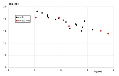
In this category, pulsating tensile and alternating shear tests are conducted with gradually decreasing load levels at a constant crack width of Δw = 0.5 mm. Table 2.2 summarizes the test conditions.
Performance category C2
Performance category C2 includes static reference tests for tensile and shear loads in cracked concrete (C2.1 and C2.2, respectively), tests under pulsating tensile load (C2.3), tests under alternating shear load (C2.4), and crack opening tests under a constant tensile load (C2.5). Crack opening tests are generally considered to be the most demanding; they are often crucial for the qualification of anchors (see [11]). Table 2.3 provides an overview of the tests required for category C2.
The cyclic tests for category C2 were developed from the point of view that both the suitability under extreme conditions (cyclic loading in wide cracks) and the serviceability of the anchor (displacement behavior and design loads) can be assessed simultaneously in a series of tests [20]. The required category C2 test series are briefly explained below.
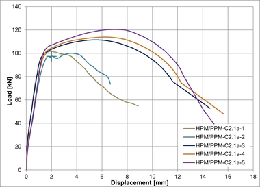
2.3.1 Reference tests under static load (series C2.1 and C2.2)
In category C2, static reference tests are first conducted under tensile and shear load. Reference tests are performed in cracked concrete with a crack width of Dw = 0.8 mm. These tests are required to determine the mean failure loads Nu,m,C2.1 and Vu,m,C2.2, which, in turn, are used to define the load curves for test series C2.3, C2.4, and C2.5.
2.3.2 Series C2.3 – Pulsating tensile load
The test procedure for anchors under pulsating tensile load can be divided into two parts: The first part of the test protocol includes the cyclic phase in which the anchors are subjected to axial tension in accordance with the procedure. The load is gradually increased in increments of 0.1 Nmax, up to the maximum load Nmax. The test starts at a crack width of Δw = 0.5 mm, which increased to Δw = 0.8 mm, which reflects the suitability test level. Upon completion of the entire load sequence, the fasteners are relieved and then statically loaded in tension until failure.
2.3.3 Series C2.4 – Alternating shear load
Similar to the pulsating tensile test sequence, the sequence for alternating shear load tests can be divided into two parts: a cyclic phase and the determination of the residual bearing capacity. In the cyclic phase, the fasteners are subjected to a sinusoidal shear load. As in test series C2.3, the load is increased gradually, starting at a load level of 0.2 Vmax and increasing it by 0.1 Vmax in each increment.
2.3.4 Series C2.5 – Constant tensile load and variable crack width
The C2.5 test series is an additional test for the seismic qualification of anchors compared to other procedures such as the category C1 tests [11]. The cyclic loading protocol shows gradually increasing crack widths, until a crack width of Δw = 0.8 mm is reached. In accordance with test series C2.3, the maximum crack width for assessing serviceability is Δw = 0.5 mm, while it amounts to Δw = 0.8 mm for assessing suitability.