Cast-in Peikko HPM-L anchor bolts exposed to fatigue loading (Part 2)
The first part of this article published in the BFT 12/2024 issue dealt with fasteners exposed to fatigue loading and explained how to determine their characteristic fatigue resistance. The second part presents the outcomes of related tests and analyses.
5 Tests and analyses
5.1 General
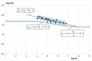
The tests summarized in Table 5.1 were conducted to investigate the fatigue behavior of Peikko HPM-L anchor bolts. In the tests, 16 mm anchor bolts made of B500B steel were used. Test specimens made of low-strength concrete of class C20/25 in uncracked and cracked condition (∆w = 0.3 mm) were used as anchorage specimens. Anchors were installed perpendicular to the concrete surface. All fatigue tests were conducted as single-stage fatigue tests. The tests under pulsating tensile and shear loads were performed with a low minimum load (Fu = 1 kN) and varying maximum loads. The alternating shear tests were conducted with a constant mean load of Fm = 0 kN. In the individual test series, the tests of HPM-L anchor bolts cast in uncracked and cracked concrete exposed to pulsating and alternating shear were conducted with different annular gap closures between the attachment through hole and the anchor bolt (see Table 5.1).
5.2 Influence of individual test parameters
5.2.1 Tensile load
The following figures show the fatigue behavior of HPM-L anchors in tension. The number of cycles applied in the tests ranged from 104 to about 6 × 10⁶. The results reveal a very clear linear trend within the tested range. In the figure below, test results are differentiated according to the concrete condition (cracked vs. uncracked). The test results demonstrate equivalence of both conditions such that the fatigue behavior is not significantly affected whether the concrete is cracked or not. This conclusion is true for up to 0.3 mm wide cracks.
In the tests, steel failure was generally observed in the anchor bolt thread near the concrete surface or in the first thread of the nut. In one test, no failure occurred at all until the limit number of cycles was reached. Fig. 5.2 shows that the numbers of load cycles to failure lie within a certain scatter range and do not differ significantly from each other.
5.2.2 Shear load
The main configuration used for shear testing was an HPM-L bolt cast in cracked concrete (0.3 mm). In addition, tests were conducted using a filling disc to show that the behavior is much more favorable. Furthermore, tests were performed in uncracked concrete to demonstrate the equivalence of the cracked and uncracked condition.
The following figures plot the HPM-L fatigue behavior in shear. The number of cycles applied in the tests ranged from 5 × 10³ to about 6 × 10⁶. The results show a clear linear trend within the tested range. The scatter is somewhat greater than in the tensile tests. The tests with and without filling disc revealed no difference, which is why the results achieved using the disc are similar. Equivalence was thus verified.
In addition, some tests were conducted for different types of loading. Most tests were performed by applying a pulsating load. Alternating load tests showed a lower fatigue strength and greater scatter compared to the test results under non-alternating loading. However, it should be noted that these tests were conducted without using a filling disc, resulting in very unfavorable conditions. Alternating load test results can lie in the same range as pulsating load test results if such a disc is used.
On the safe side, the resistance is determined as follows for alternating loads: For pulsating loads, fatigue resistance is derived as a function of the load cycles and then divided by a factor of 2 to account for alternating action. This corresponds to a load distribution in which only one anchoring element is used for each direction of loading. The test results for cracked concrete are slightly lower than those found for uncracked concrete (with the exception of alternating load tests). This is why most tests were conducted in cracked concrete. Further analyses [17] revealed that the different failure locations for all modes of steel failure did not differ significantly from each other either.
5.3 Linearized S-N curves
The test results in tension and shear were analyzed in accordance with the method described in section 4.1.4 or in the EAD [10]. For the different load directions, the diagrams below show the following parameters:
a) the test results on a log-log scale
b) the mean trend line with the scatter range (90% confidence interval)
c) the determined 5% quantile line with the relevant support points for steel failure
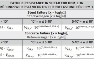
Table 5.2 and Table 5.3 summarize the resulting parameters for the linearized fatigue curves and different failure modes. These are included in the ETA and can be used for the design in accordance with TR 061 [7].
6 Summary
Anchors and inserts such as anchor channels and headed anchor bolts are anchoring systems frequently used in the construction industry to transfer loads into concrete components. In conventional reinforced concrete construction, such fasteners are mainly exposed to static or quasi-static loads. However, applications in which cyclic loads must be considered are becoming increasingly important owing to more and more slender structures and modern machinery and plant systems. Typical uses specified in EN 1992-4 [1] include fasteners for elevators, cranes, crane runways, and machines with moving parts. In such cases, fatigue verification must be conducted to prevent failure of the anchorage and connected components because of material fatigue.
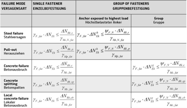
EN 1992-4 [1] specifies the design of fasteners in concrete components. For fasteners frequently exposed to repetitive load cycles, this standard requires verification of fatigue resistance. The verification under fatigue loading is based on the partial safety factor concept in accordance with the design rules specified in the Eurocodes [15]. Accordingly, design actions must be verified to be less than or equal to the design resistance. Verification is conducted separately for each load direction and potential failure mode to account for the different failure mechanisms. Different components, geometries, materials, and manufacturing processes mean that the fatigue resistance of fasteners is dependent on the specific product. Suitability of products to be used under fatigue loading must thus be verified using appropriate test and assessment methods.
The test and assessment methods for post-installed fasteners were transferred to anchor bolts [10]. Simultaneously to drafting the guideline, the corresponding tests were conducted for Peikko HPM16-L anchor bolts [11]. As expected, the tests showed a positive result. European Technical Assessment ETA 02/0006 [3] has recently been revised to include the characteristic values for seismic and fatigue loading, and published [5].



![Table 5.1: Test program for HPM-L anchor bolts [11]](https://www.bft-international.com/imgs/2/1/8/4/4/3/0/tok_7693271559cb5b9a38da6e599cedc619/w300_h200_x381_y247_Peikko_1-c00649306b0e28c0.jpeg)

